PNP and NPN sensors
I was wondering how is the interfacing with PNP and/or NPN industrial sensors and Industruino IND board. Is there any extra components needed? which kind of output can I read with the digital inputs on this board?
What about the digital outputs on the board are they open collector or what? I searched the website for the information about that but I could not find detailed information on the schematics. Maybe I've missed them.
Please advise,
Hi Amir, PWM is not supported on the 12/24V digital outputs. You can however use some of the standard 5V Arduino PWM pins which can be found on the 14pin IDC expansion connector. If you need a true analog signal instead of PWM you have 2 0-10V/4-20mA output channels on the analog side.

Hi, I would like to generate a pulse(on-off) with 10-60Hz on one of the digital outputs of this board. I need to trigger a 24v input on the other device with it. So what you are saying is that I can not switch pins on the MOSFET located on the output of Industrino that fast? -- Best regards Amir On Mar 3, 2015, at 11:31 AM, Loic De Buck wrote: Hi Amir, PWM is not supported on the 12/24V digital outputs. You can however use some of the standard 5V Arduino PWM pins which can be found on the 14pin IDC expansion connector. If you need a true analog signal instead of PWM you have 2 0-10V/4-20mA output channels on the analog side.

Hello Amir,
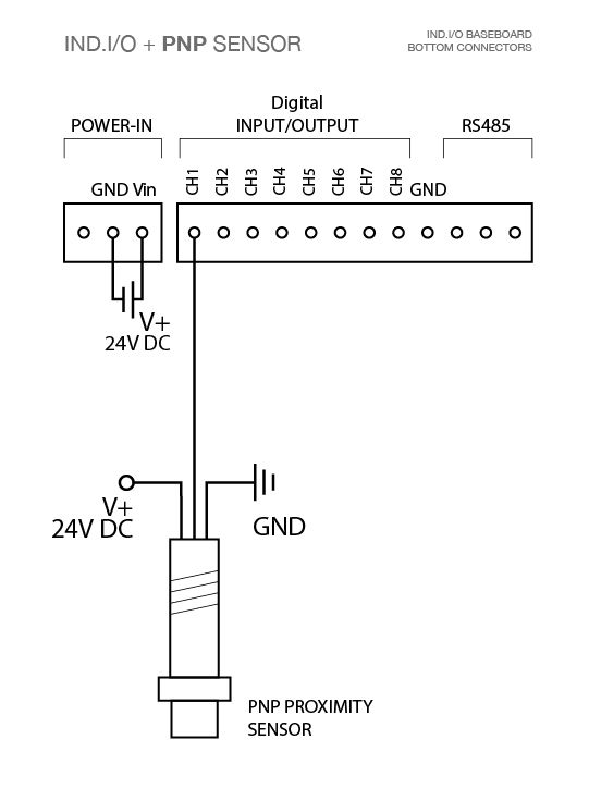
Please have a look at the wiring diagrams for PNP and NPN sensors below. So when using PNP sensors there is no need for any external components, when using NPN sensors you need an external pull-up resistor. Any kind of 12V or 24V digital output signal can be read with the IND.I/O board.
The 12/24V digital outputs are driven by Infineon ITS716G high-side drivers. Each of the 8 channels can drive 2.3A, with a total of 6.5A for multiple channels at the same time (limited by the board and fuse characteristics).
UPDATE:
Although the high-side drivers don't support PWM mode they can be switched fairly fast, more than enough for your application. To confirm this I've tested this with following code:
WARNING!: PLEASE BE VERY CAREFUL WHEN CONNECTING PERIPHERALS TO YOUR IND.I/O AND CONFIGURING THE DIRECTION OF THE I/O.
THE FAILURE MODE OF A 24V SHORTED CONNECTION IS MUCH MORE SPECTACULAR THAN WHEN WORKING AT 5V.*/
#include <Indio.h>
#include <Class_define.h>
#include <Wire.h>
#include <TimerOne.h>
long previousMillis = 0;
long pulseWidth = 5; // interval at which to blink (milliseconds)int pulseFlag = 0;
void setup()
{Indio.digitalMode(8,OUTPUT); // Set CH8 as an output
Timer1.initialize(20000); // set a timer of length 20 miliseconds, determines the period of the pulse.
Timer1.attachInterrupt( timerIsr ); // attach the service routine here
}void loop()
{
unsigned long currentMillis = millis();
if (pulseFlag == 1) //check if its time for a new pulse (set by interrupt).
{
Indio.digitalWrite(8,HIGH); // Set CH8 to high (24V, or whatever your Vin voltage).
pulseFlag = 0;
previousMillis = currentMillis;
}
if(currentMillis - previousMillis > pulseWidth) { //keep checking when to end the pulse's on time.
Indio.digitalWrite(8,LOW); // Set CH8 to LOW
}
}
void timerIsr()
{
pulseFlag = 1; // set a flag to trigger a pulse
}
A screenshot of the resulting wave as captured by my oscilloscope can be seen below.
Cheers,
Loic
Your answer
Please try to give a substantial answer. If you wanted to comment on the question or answer, just use the commenting tool. Please remember that you can always revise your answers - no need to answer the same question twice. Also, please don't forget to vote - it really helps to select the best questions and answers!
Keep Informed
About This Forum
This community is for professionals and enthusiasts of our products and services.
Read GuidelinesQuestion tools
Stats
| Asked: 3/2/15, 10:13 PM |
| Seen: 16930 times |
| Last updated: 5/22/15, 3:03 AM |


Thanks for the your comprehensive answer. In case I want to use generate a pwm signal can I use the standart arduino library/command? Or do I need some specific library?