To illustrate how easy it is to move from an Arduino breadboard project to a nice enclosed application
The end result:
- DC/DC converter driven by a digital potentiometer and PID control
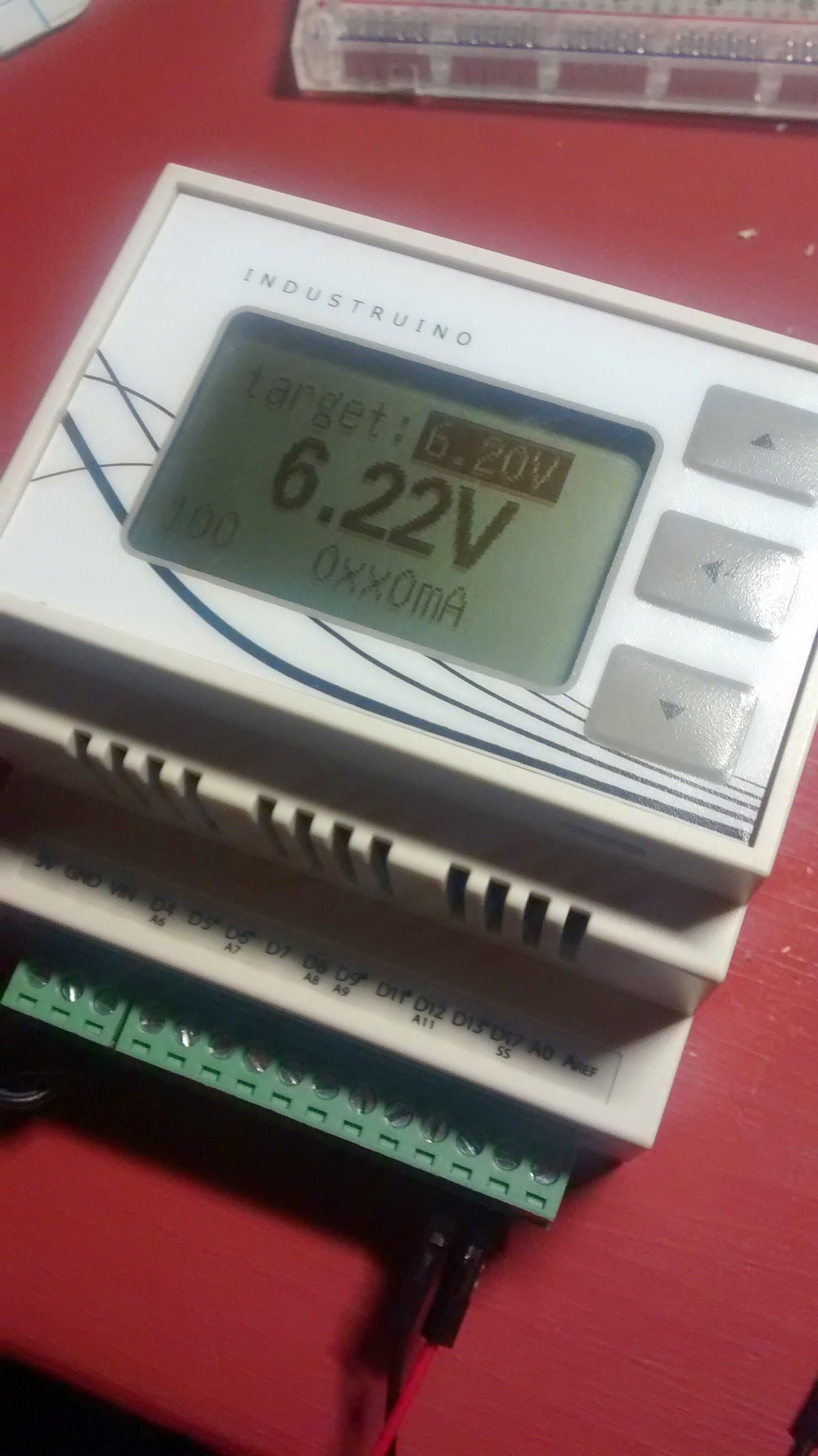
- Set target voltage with the buttons on the Industruino panel: up/down and enter to confirm target voltage
- Shunt resistor with opamp to measure the current (0-250mA range)
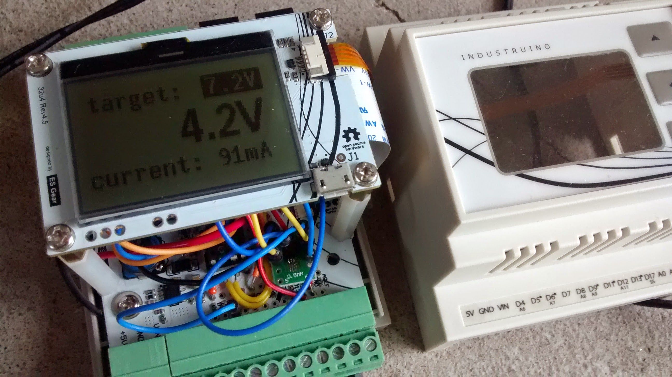
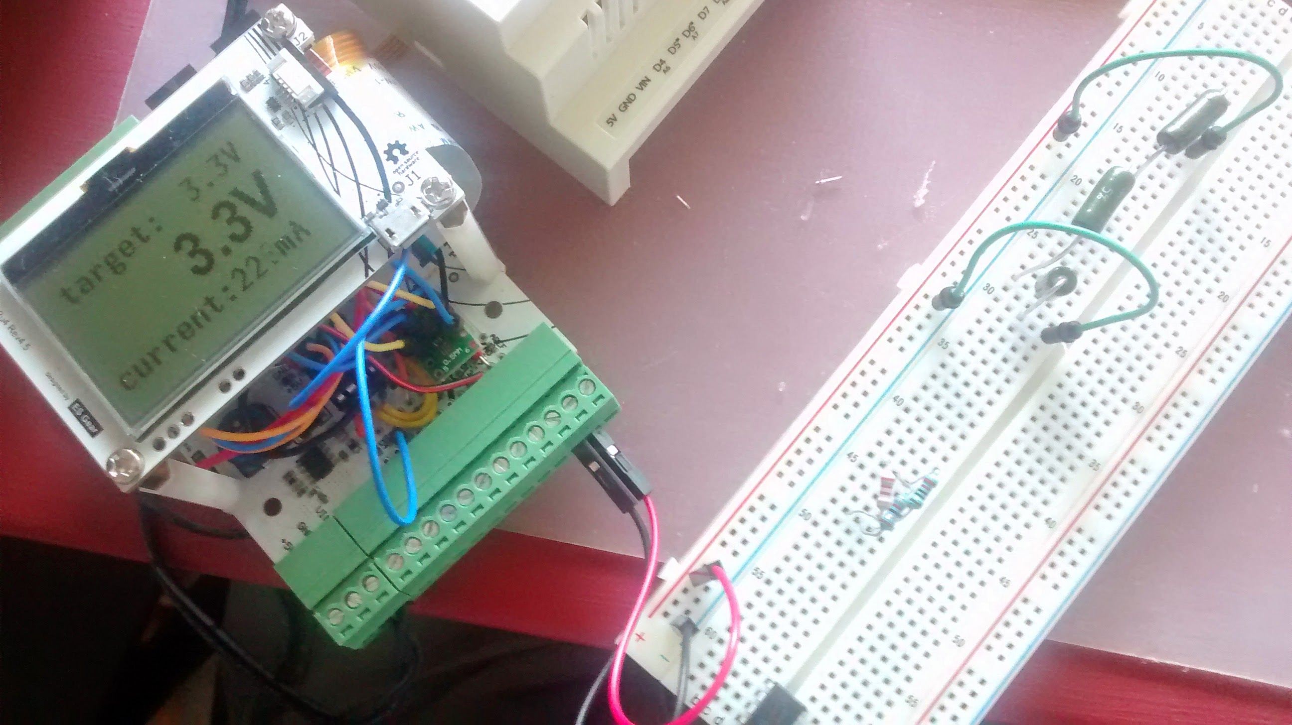
- LCD shows target voltage, output voltage, output current
- DIN-rail mountable robust housing for Arduino project
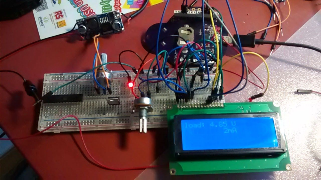
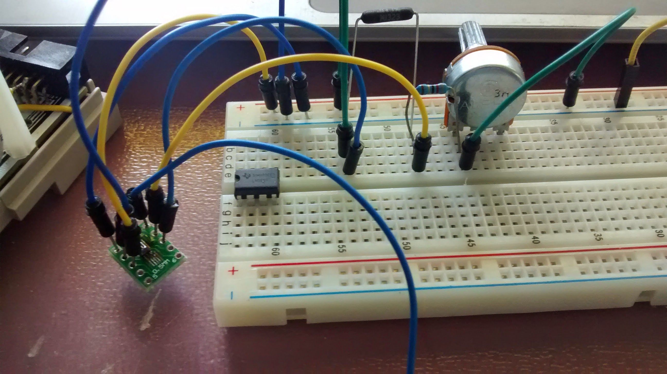
Digital power supply prototype on a breadboard
This picture shows the first phase of the project: a common DC/DC converter in the top left, from which I took out the trim pot, and add a potentiometer on the breadboard to control the output voltage. I used an Arduino Leonardo (in the back) to add an LCD screen, and a shunt resistor to measure the load current.
Next I replaced the potentiometer with digital potentiometer MCP4151, which uses SPI, and added a PID controller in my Arduino sketch to drive the dig pot.
As soon as this was working on the breadboard, I moved the components to the PROTO baseboard.
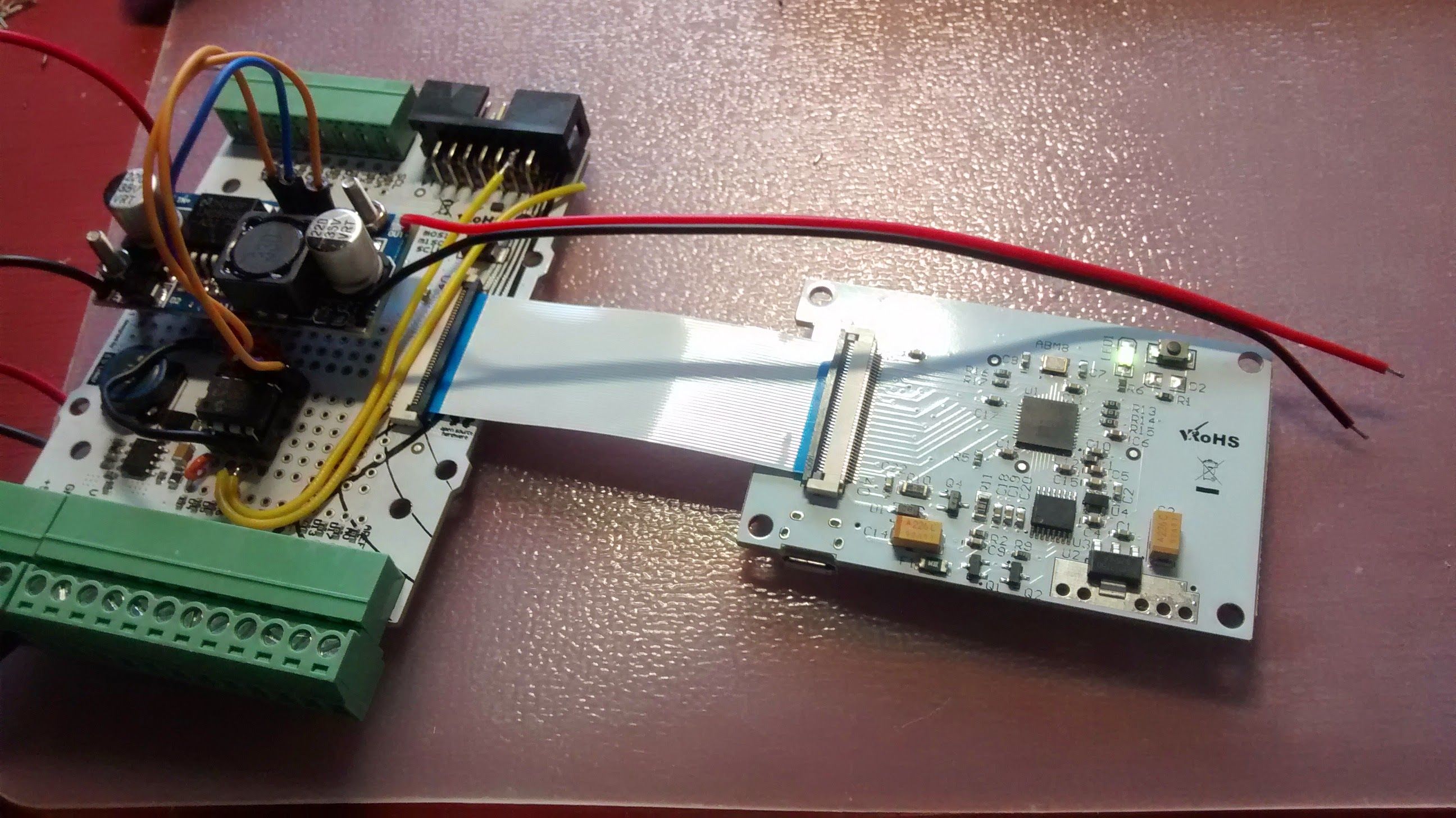
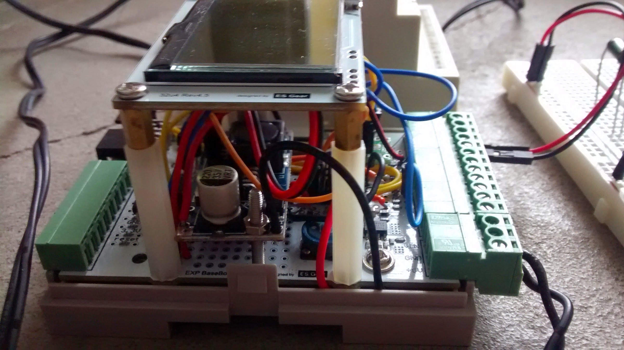
PROTO baseboard
The baseboard has plenty of space to add components; I put the DC/DC converter in a central position to be sure to have enough height available in the box. I drilled 2 holes to fasten this PCB.
I connected a 12V DC wall wart to the Industruino's Vin and I took the Industruino Vin and GND from the bottom side of the baseboard, going into the DC/DC converter.
The 2 orange and 1 blue wire connect the DC/DC to the dig pot on the baseboard. The dig pot also has a connection to the Industruino's regulated 5V, and the SPI pins avaible on the black expansion connector.
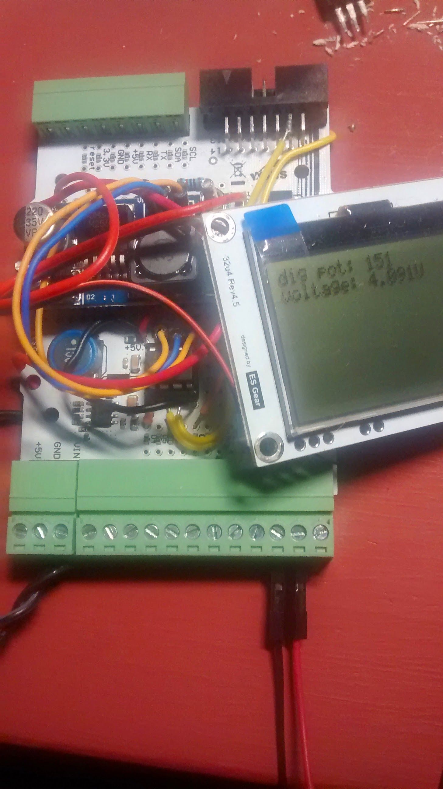
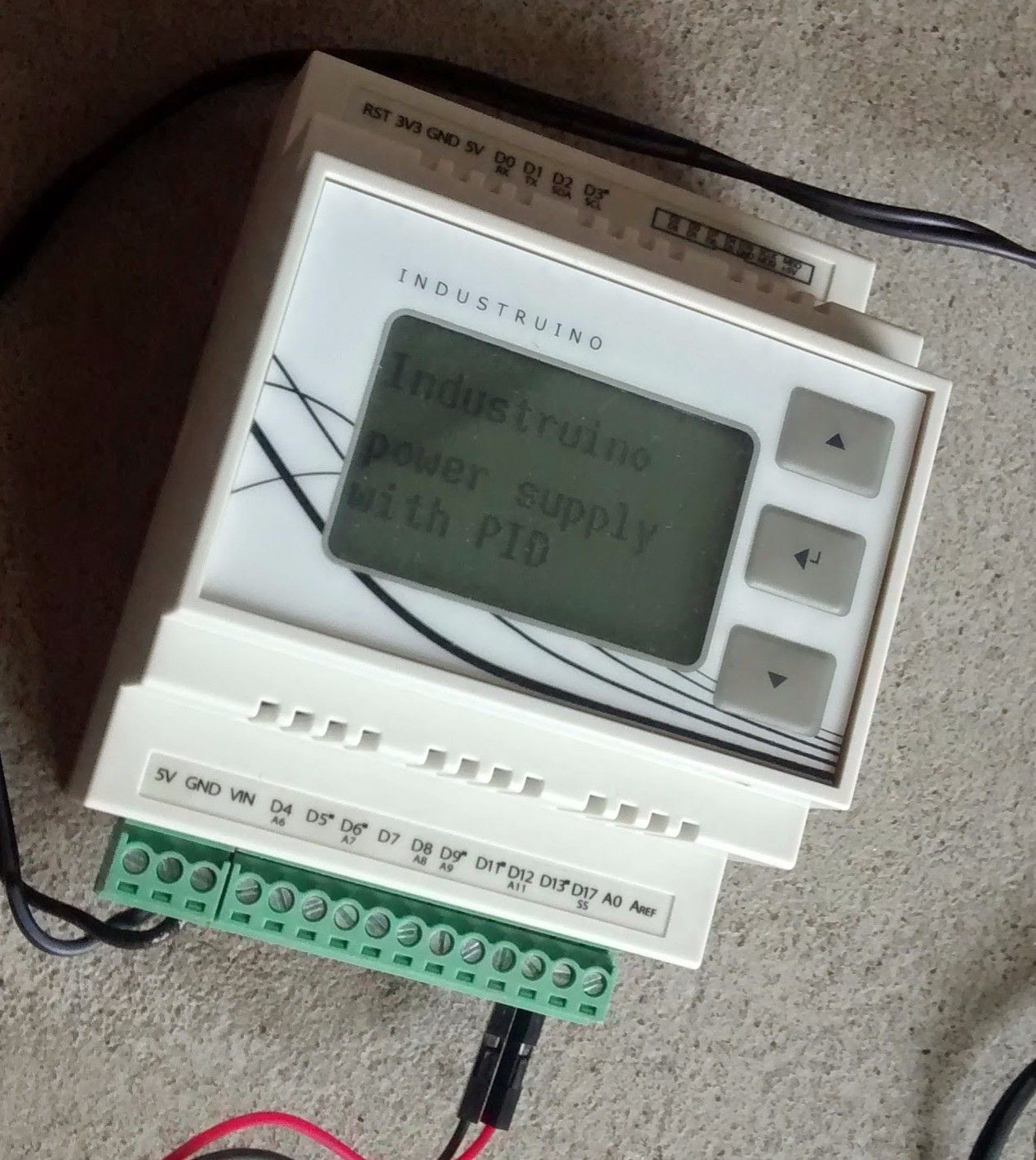
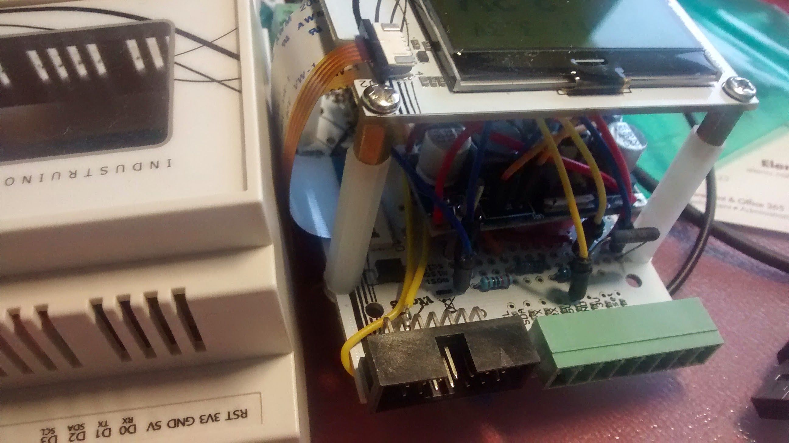
Connecting the Industruino
Now I was ready to test this setup, using the standard Industruino sketch with the UC1701 LCD library.
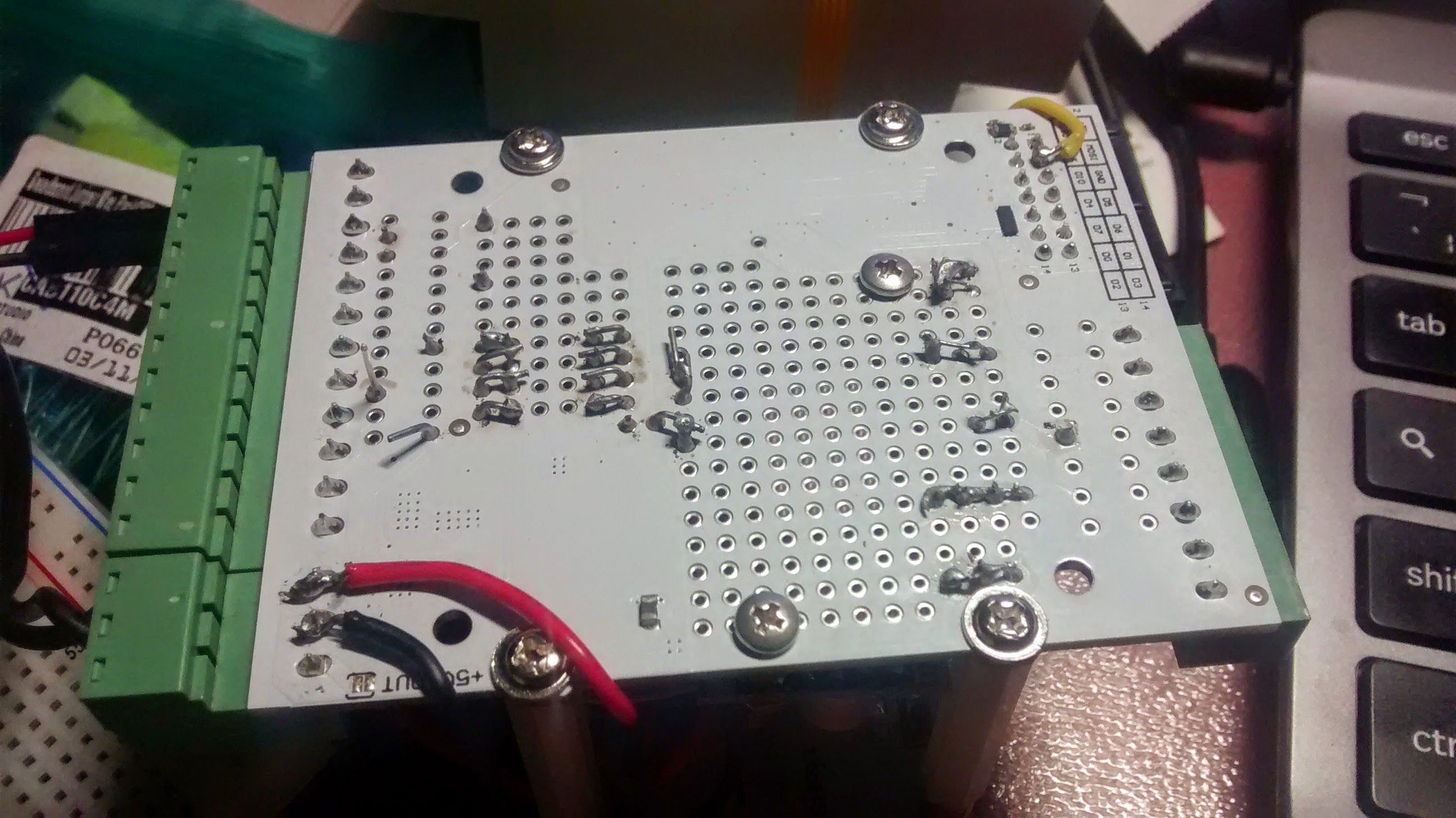
For the wall wart Vin, I used the Industruino's terminal block as in this picture, lower left. I also wanted to use the terminal block for the DC output, so I connected a red and black wire to the terminal block as in the lower right. These connections are normally used as D17 and A0, but the baseboard has handy 0 ohm resistors to disconnect the terminal block from the Arduino pins. In this way, the terminal blocks can be used for anything else.
Using the U8G display library
I wanted the show the voltage in a large font, so I decided to use the U8G library. The Leonardo compatible Industruino topboard only has about 29kB space for the sketch, which can easily be insufficient if you don't use the U8G fonts carefully.
I decided to use only 2 fonts: one for the small text (u8g_font_9x18B - a nice bold font) and one for the large voltage display (u8g_font_fub20). For this last one I only need the numbers and the letter 'V' so I could use the reduced font set (u8g_font_fub20r) which uses a lot less memory. If you only need numbers, you can use an even smaller one (u8g_font_fub20n).
With these 2 fonts, my final sketch was just below 25kB so it fits nicely in the Industruino's ATmega32u4.
In this first version, I did not include current measurement yet, as my initial solution with a shunt resistor on the high side, and analog measurement of the 2 voltages (both sides of the shunt resistor) versus GND, did not give a good resolution.
Current shunt monitor
In order to have a good resolution on the voltage reading across the high side shunt resistor, I used the specialised Texas Instruments INA210 opamp with standard 200 gain. For the shunt resistor I chose 0.1 ohm (1W). I connect the output of the opamp to an analog pin on the Arduino, with Aref 5V, so the maximum voltage that I can read over the shunt resistor is 25mV (5V/200). From Ohm's law it follows that the maximum current I can read is 250mA; any higher currents will clip the analog input, but not cause any damage.
The INA210 unfortunately only comes in a SC70 package, which is quite hard to solder onto a breakout board. I tested the IC on a breadboard first, as in this picture, with the black shunt resistor in the center top.
When this was working, I was ready to move the INA210 to the PROTO baseboard.
Adding the opamp for current measurement
I found some space next to the dig pot to add the breakout with the INA210 opamp, and connected the it to 5V and GND, and across the shunt resistor. The output goes straight into pin D6/A7 for analog reading.
The voltage divider and shunt resistor
On the upper side of the baseboard I put a voltage divider of 3x 10kOhm resistors, to bring the DC output voltage in the range of 0-5V for analog reading.
The 0.1 Ohm shunt resistor is on the right side, on the so-called 'high' side between the DC output and the load. This allows the DC output to share GND with the power supply, but necessitates an opamp to get good resolution on the current measurement.
Ready to close the box and start using my Industruino digital power supply!