Proximity sensor are very common in industrial applications so we will provide an example here on how to use with the Industruino IND.I/O. These sensors come in 3 main types: magnetic, inductive, capacitive, according to the material we want to detect. We will use inductive sensors in this example to react to metal (and magnets).
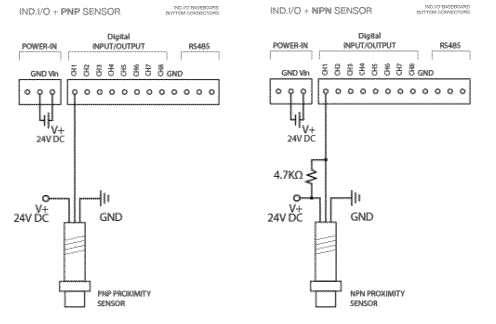
There are sensors with 2 wires which act as a switch, but more common are 3 wire sensors as in the banner picture above. They come in 2 types: PNP and NPN. If you have the choice, PNP types are more convenient for the INDIO, because they require no additional components: the PNP type provides a HIGH signal when active.
The NPN type requires a pull-up resistor (between V+ and the input channel) to ensure the channel is HIGH; the sensor will pull the channel LOW when active, so the logic is inverted. The suggested value of the pull-up resistor for 24V systems is 4K7ohm, drawing around 0.1W when the sensor pulls the channel LOW. A 1K resistor would draw 0.5W which would be too much for a standard 1/4W resistor.
See the figure on the left for the wiring of PNP and NPN sensors. More information is also available in this earlier blog post.
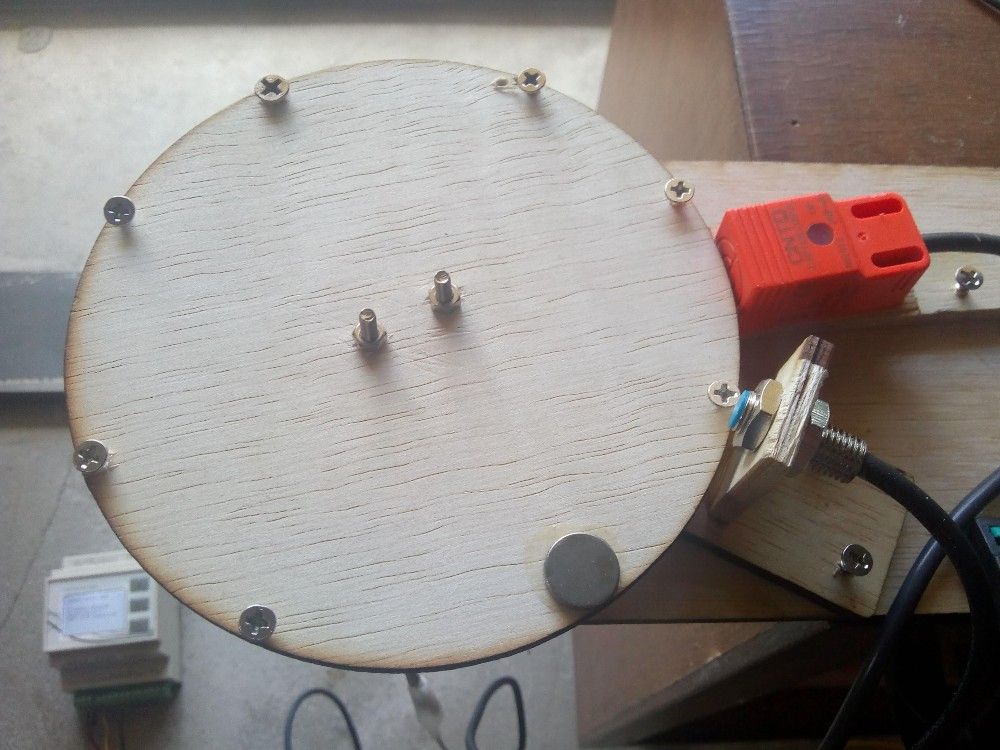
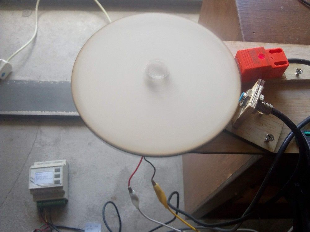
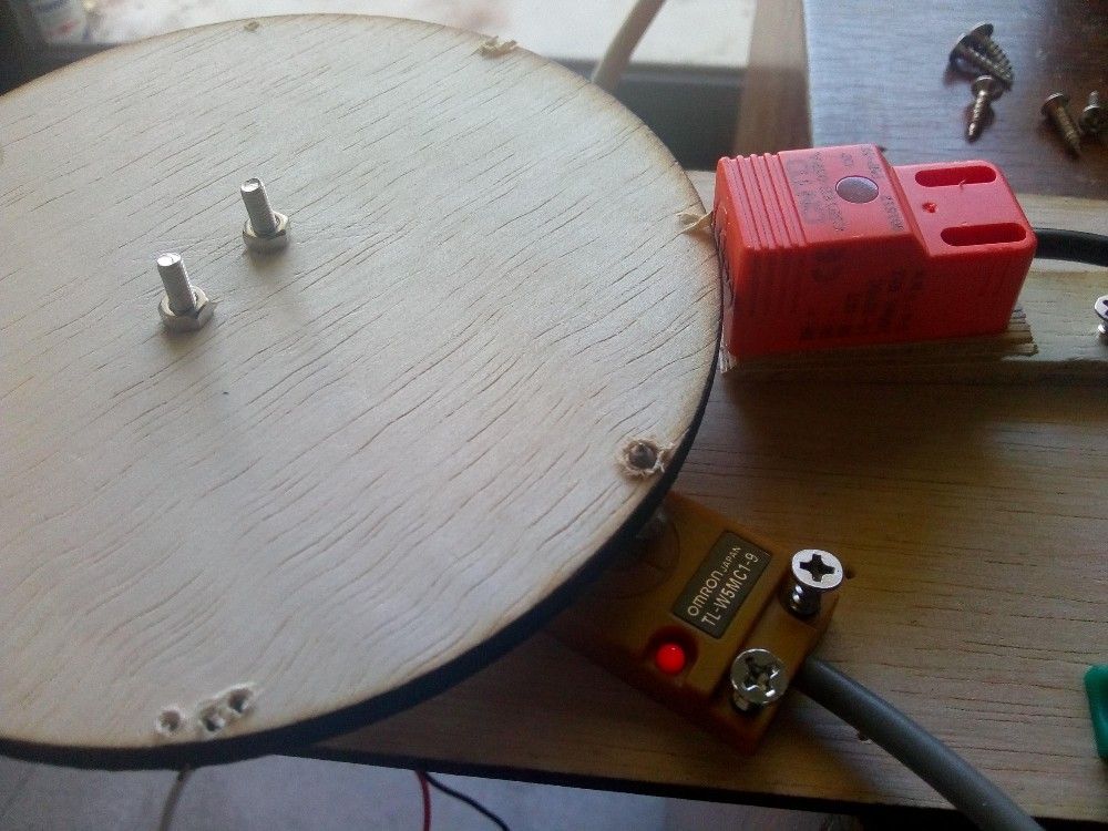
In this example, we will measure the speed (RPM) of a rotating disk.
PNP inductive sensor: the orange sensor is a CNTD CJF18E-05PA which is perfectly suitable for use with the INDIO as no additional components are required. Sensing distance is 5mm and it reacts to metals (and magnets).
NPN magnetic sensor: the blue tipped sensor is a no-brand magnetic sensor that requires a pull-up resistor, i used 5K.
Both sensors have a built-in red LED to show their active status (detection).
Click here for a video that shows how the 2 sensors react.
To measure the speed accurately, we need to use interrupts, as we want to be sure to catch every pulse generated by the sensors. The INDIO can trigger a general Arduino-style interrupt when any of the input channels changes state. By default this interrupt is triggered by a change on any input channel, but channels can be MASKED if they should not trigger the interrupt (see documentation).
ONE CHANNEL
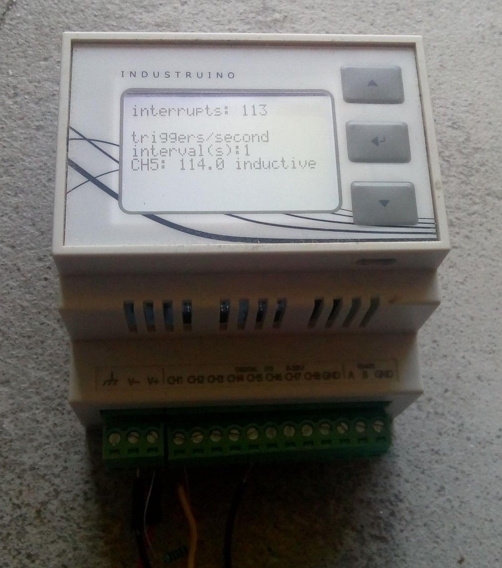
The simplest situation is when we only need to count pulses on 1 channel; then we can configure the interrupt to be triggered by that channel only, and we can measure high speeds. In the video below we get around 114 pulses per second, which would be 6840 RPM if there was only one pulse per rotation, but we have 8 (7 screws + 1 magnet). Click here for a video.
This is the sketch used for above experiment.
/*
 * Industruino INDIO test with PNP sensor
 * measure speed of a rotating disk: count pulses per second using an interrupt counter
 */

#include <Indio.h>
#include <Wire.h>

#include <UC1701.h>
static UC1701 lcd;

volatile int counter = 0;

const float sec = 1;

////////////////////////////////////////////////////////////////////////////////////

void setup() {

  lcd.begin();

  pinMode(26, OUTPUT);  // LCD backlight
  digitalWrite(26, HIGH); // backlight on to start

  for (int i = 1; i < 9; i++) {   // clear the input channels 1-8 by writing LOW
    Indio.digitalMode(i, OUTPUT);
    Indio.digitalWrite(i, LOW);
  }

  /*
    Indio.digitalMode(1, INPUT);                  // default: input with interrupt without latch
    Indio.digitalMode(2, INPUT_LATCHED);          // input with interrupt and latch
    Indio.digitalMode(3, INPUT_MASKED);           // input without interrupt
    Indio.digitalMode(4, INPUT_LATCHED_MASKED);   // input with latch without interrupt
  */
  Indio.digitalMode(5, INPUT);

  attachInterrupt(8, count_ISR, FALLING);       // D8 attached to the interrupt of the expander

}

////////////////////////////////////////////////////////////////////////////////////

void count_ISR() {
  counter++;
}

////////////////////////////////////////////////////////////////////////////////////

void loop() {

  lcd.setCursor(0, 0);
  lcd.print("interrupts: ");
  lcd.print(counter);

  lcd.setCursor(0, 2);
  lcd.print("triggers/second");
  lcd.setCursor(0, 3);
  lcd.print("interval(s):");
  lcd.print(sec, 0);

  lcd.setCursor(0, 4);
  lcd.print("CH5: ");
  lcd.print(counter / sec, 1);
  lcd.print(" inductive  ");

  counter = 0;

  delay(sec * 1000);

}
TWO CHANNELS
In case we want to measure more than 1 speed, still using the interrupt mechanism, we need to write a bit more code to determin which channel triggered the interrupt.
For this experiment i used the same CNTD PNP inductive sensor, and also an OMROM NPN inductive sensor, model TL-W5MC1. To trigger this sensor i put a screw in the disk, from the bottom, which does not trigger the orange sensor. The NPN sensor needs a pull-up resistor, e.g. 4K7.
The code works as follows:
- we define the 2 channels (1 and 5) as INPUT_LATCHED; this means when the input signal changes, the INDIO will keep this new value until we use the Indio.digitalRead() function. if the input signal changes before we read the value, the latched value will be kept. so a pulse is stored in this latched value, and we can read it later, we just have to make sure to read it before a new pulse occurs otherwise that new pulse will go unrecorded.
- we activate the general interrupt, which will set a flag whenever a channel changes. we cannot do the Indio.digitalRead() inside the ISR as it takes too long and would freeze the unit.
- in the main loop, we check the flag. if the flag is set, it means we should read the 2 channels and compare them with their previous value to find out which one has changed.
- we measure over an interval of 5 seconds to calculate the 2 speeds.
This is the code for the 2 channel experiment:
/*
* Industruino INDIO test with PNP and NPN sensors
*
* measure 2 speeds: the interrupt will fire by any of the 2 sensors
* set a flag when the interrupt fires
* in main loop, if flag is set, check which sensor has changed and increase counter
* after an interval, display the 2 speeds and reset the counters
*
* Tom Tobback Aug 2019
*/

#include <Indio.h>
#include <Wire.h>

#include <UC1701.h>
static UC1701 lcd;

volatile int counter = 0;
volatile int count1 = 0;
volatile int count5 = 0;
volatile boolean flag = 0;

boolean now_state1;
boolean now_state5;
boolean prev_state1;
boolean prev_state5;
unsigned long timestamp;
const float sec = 5;

////////////////////////////////////////////////////////////////////////////////////

void setup() {

  lcd.begin();

  pinMode(26, OUTPUT);  // LCD backlight
  digitalWrite(26, HIGH); // backlight on to start

  for (int i = 1; i < 9; i++) {   // clear the input channels 1-8 by writing LOW
    Indio.digitalMode(i, OUTPUT);
    Indio.digitalWrite(i, LOW);
  }

  /*
    Indio.digitalMode(1, INPUT);                  // default: input with interrupt without latch
    Indio.digitalMode(2, INPUT_LATCHED);          // input with interrupt and latch
    Indio.digitalMode(3, INPUT_MASKED);           // input without interrupt
    Indio.digitalMode(4, INPUT_LATCHED_MASKED);   // input with latch without interrupt
  */
  Indio.digitalMode(1, INPUT_LATCHED);
  Indio.digitalMode(5, INPUT_LATCHED);

  pinMode(8, INPUT_PULLUP);   // D8 is interrupt pin of INDIO's digital I/O expander
  attachInterrupt(8, count_ISR, FALLING);       // D8 attached to the interrupt of the expander

}

////////////////////////////////////////////////////////////////////////////////////

void count_ISR() {
  counter++;
  flag = true;
}

////////////////////////////////////////////////////////////////////////////////////

void loop() {

  if (flag) {

    detachInterrupt(8);   // detach the interrupt while we are reading and updating the flag

    now_state1 = !Indio.digitalRead(1);   // NPN type  on = low, so invert reading

    now_state5 = Indio.digitalRead(5);    // PNP type: on = high
    flag = false;

    attachInterrupt(8, count_ISR, FALLING);       // D8 attached to the interrupt of the expander

if (now_state1 == HIGH && prev_state1 == LOW) {
      count1++;
    }
    if (now_state5 == HIGH && prev_state5 == LOW) {
      count5++;
    }
    prev_state1 = now_state1;
    prev_state5 = now_state5;

  }

  if (millis() - timestamp > sec * 1000) {
    lcd.setCursor(0, 0);
    lcd.print("interrupts: ");
    lcd.print(counter);

    lcd.setCursor(0, 2);
    lcd.print("triggers/second");
    lcd.setCursor(0, 3);
    lcd.print("interval(s):");
    lcd.print(sec,0);

    lcd.setCursor(0, 4);
    lcd.print("CH1: ");
    lcd.print(count1 / sec, 1);
    lcd.print("  NPN ");

    lcd.setCursor(0, 5);
    lcd.print("CH5: ");
    lcd.print(count5 / sec, 1);
    lcd.print("  PNP ");

    count1 = 0;
    count5 = 0;

    timestamp = millis();
  }

}
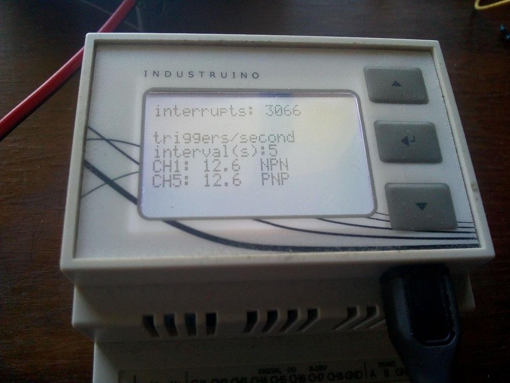
The LCD screen shows the total number of interrupts, and the 2 speeds in rotations per second. It refreshes the screen every 5 seconds.
There is an upper limit to the speeds we can measure using this method: at higher speeds the interrupts start to interfere with the Indio.digitalRead() commands. Speeds up to 10 rotations per second (600RPM) seem stable, but that also depends on what else the sketch needs to do in the main loop.
Click here for a video of the rotating disk with 2 inductive sensors PNP and NPN measuring the same speed. The maximum error should be 0.2 rotations: 1 pulse per interval of 5 seconds.