Industruino IND.I/O D21G
30-day money-back guarantee
Shipping from Belgium or HK
Currently out of stock
Deliveries expected to resume 22/4/2026
Description
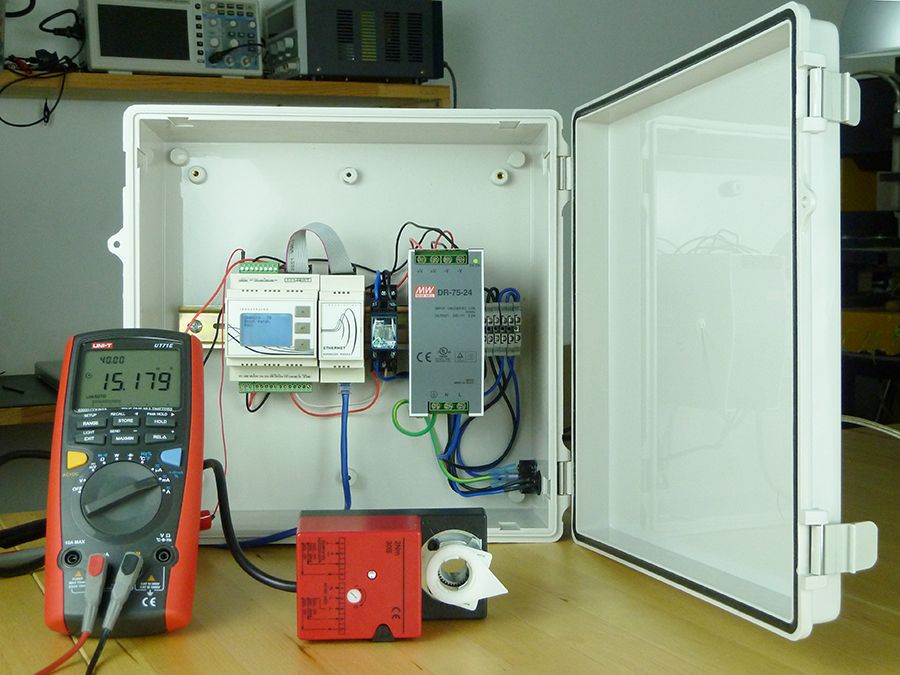
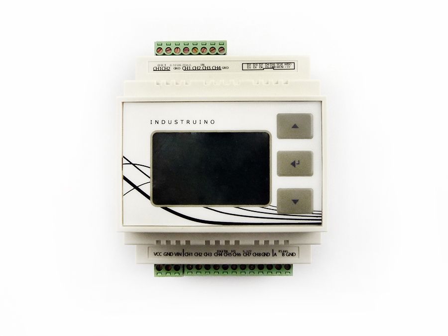
The IND.I/O D21G controller is a robust DIN-rail mountable Arduino IDE compatible controller with isolated industrial level I/O capability.
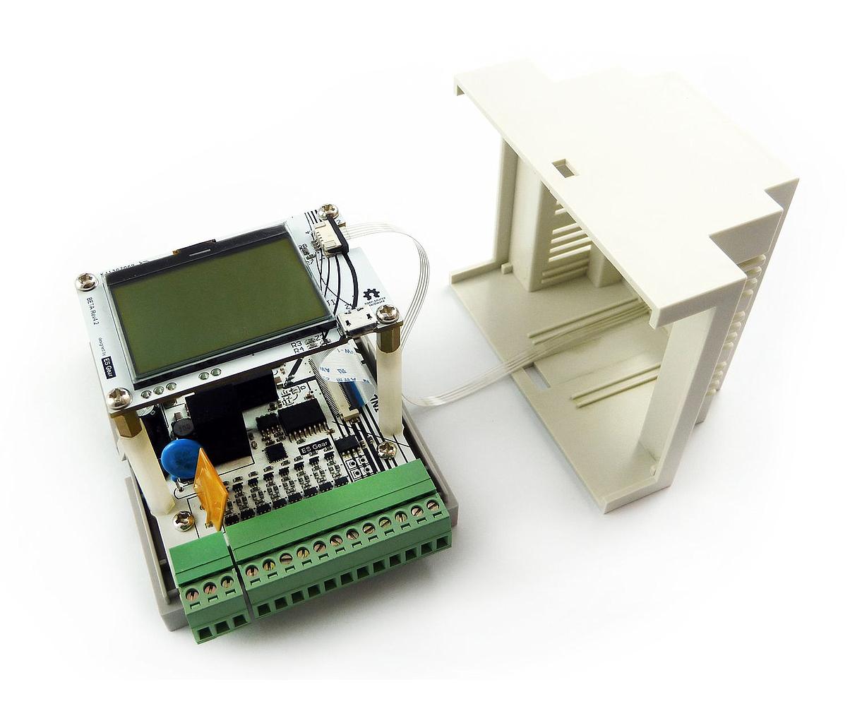
Parts included are:
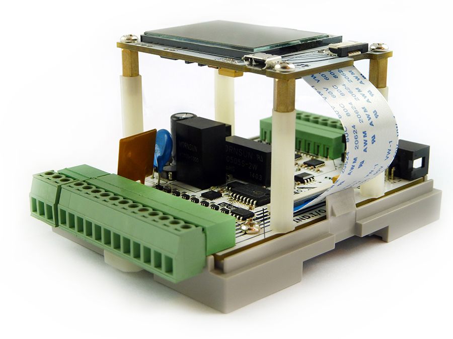
- D21G Topboard (Arduino Zero/MKR equivalent microcontroller)
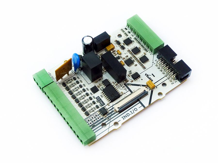
- IND.I/O Baseboard (Industrial level isolated I/O interface board)
- DIN-rail enclosure with membrane button panel.
- Plug-in screw connectors
The controller comes fully pre-assembled and ATE tested.
Weight (kg): 0.2
Tariff no: 85371091
Product Features
- Industrial I/O levels (24V digital I/O, 0-10V/4-20mA analog I/O)
- Isolated RS485 transceiver
- All I/O and power available through detachable screw connectors
- DIN-rail mountable
- Fully enclosed
- 128x64 pixels LCD with backlight
- 3 button membrane panel
- Pre-loaded with interactive LCD menu firmware (code examples available for download on our github)
- Fully compatible with the Arduino IDE
Isolated Zones of Ind.I/O
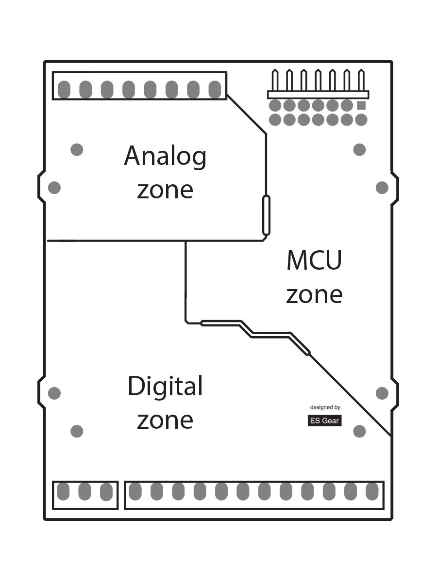
Analog field section
- Analog Input Channels: 4
- Analog Output Channels: 2
- Analog levels: 0-10V/4-20mA (switchable in software)
- Analog Input resolution: 18 bit
- Analog Output resolution: 12 bit
- Fully isolated from MCU and digital side (1kV isolation)
Digital field section
- Supply voltage: 8-28V
- Digital I/O Channels: 8
- Digital input voltage range: 3.3-28V
- Digital output voltage range: Tied to Vin (8-28V)
- Output current per digital pin 2.3A (Short circuit, over-current, over-temp protected).
- Total output current: 6A (omni block fused)
- Fully isolated from MCU and analog side (1kV isolation)
- Half Duplex RS485 transceiver
MCU section
- MCU Type: ATSAMD21G Arduino Zero/MKR equiv.
- Flash Memory 256 KB
- SRAM 32 KB
- EEPROM 1 KB
- Clock Speed 48 MHz
- MCU Operating Voltage 3.3V / 5V tolerant
- U8G & UC1701 library compatible LCD
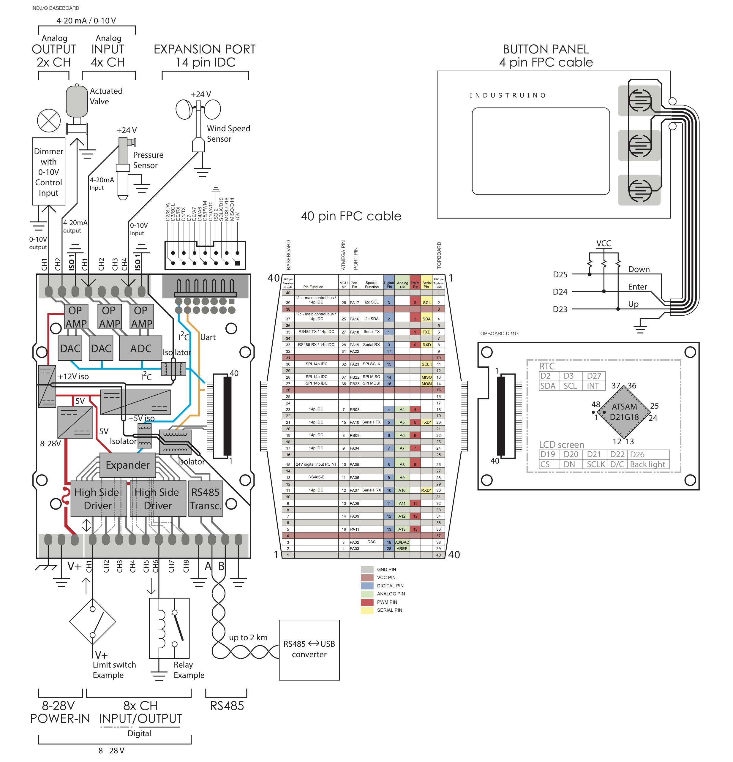
- 3 button membrane panel connected to pins D23-D25.
- LCD backlight PWM controlled via pin D26.
- Battery backed RTC with scheduled interrupts.
- TFTP Ethernet bootloader
Documentation
Pinout diagram
Downloads
Industruino Ind.I/O support files
The Industruino IND.I/O libraries and board definition files can be downloaded here