The PT100 and PT1000 are standard industrial temperature sensors (RTD = Resistance Temperature Detectors) that can easily be used with an Industruino INDIO by adding a 4-20mA transmitter that converts the measured resistance into a 4-20mA signal.
The PT100 sensor comes with 2, 3, or 4 wires. 2 wires give us the resistance of the sensor PLUS the leads, so we can't be sure about the exact sensor resistance. 3 wires solve this by adding a wire to one side, so we can measure also the resistance of 1 lead wire, and assume the other one is similar. 4 wires allow us to measure the resistance of both lead wires. More details here.
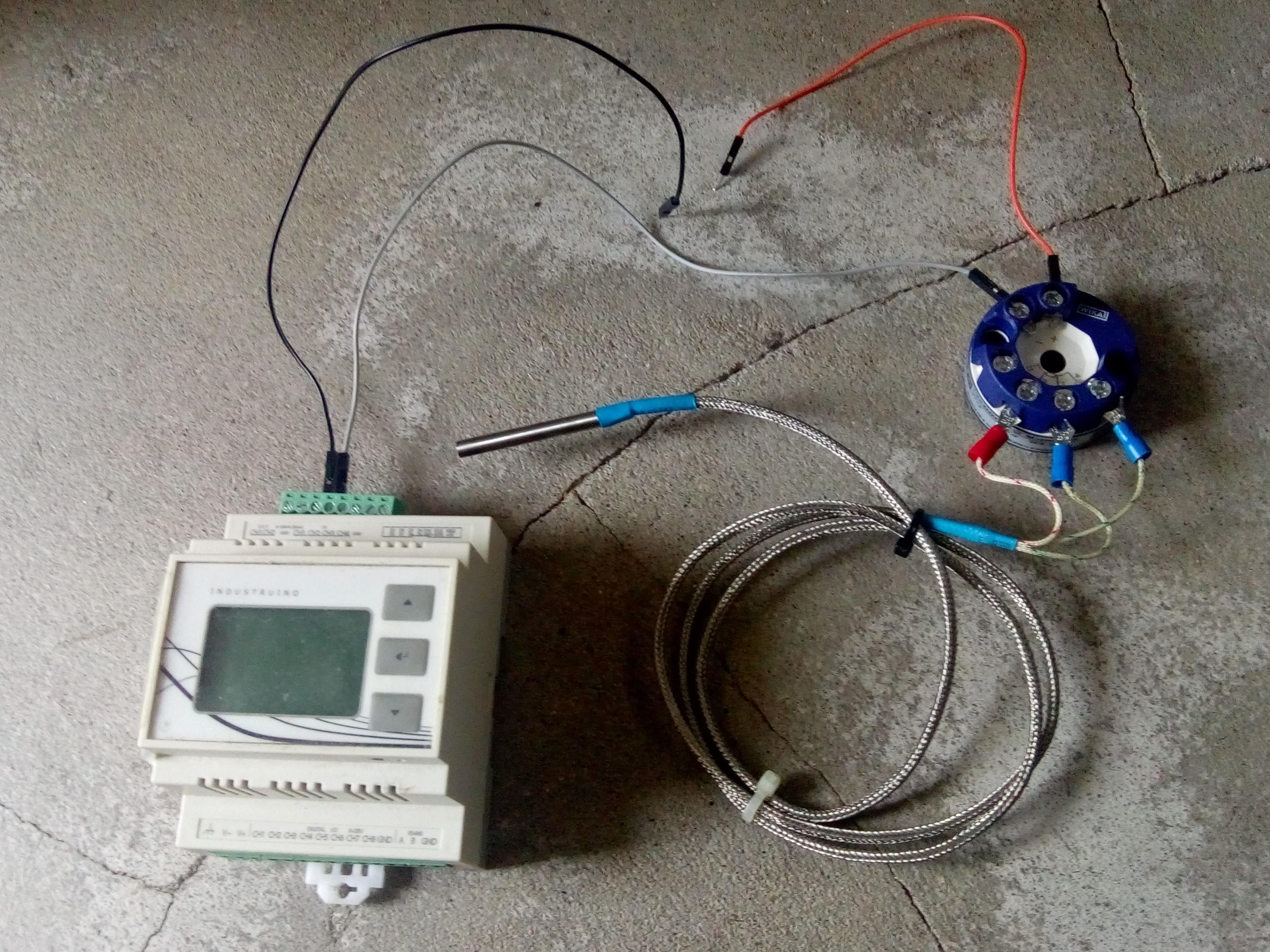
A common way to use the PT100 is to add a transmiter, that converts the resistance into a 4-20mA signal. Such current loop is stable over long cable lengths. In this example we use a WIKA T15.H transmitter which can handle 2,3,4 wire PT100 and PT1000 sensors, and has programmable ranges and error handling (if you get the programmer).
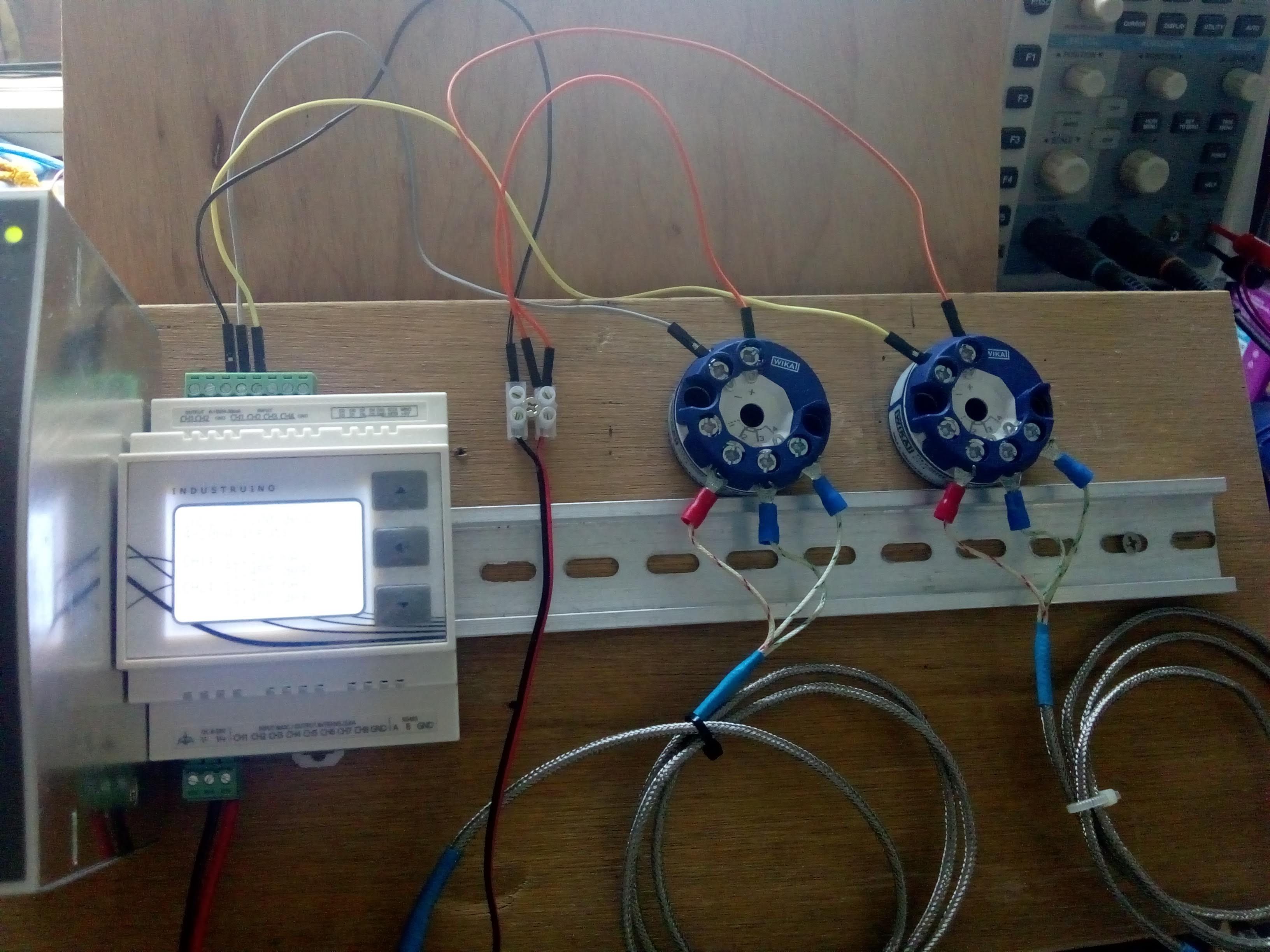
The INDIO has 4 analog input channels, so we can connect up to 4 PT100 sensors. In below example we connect 2.
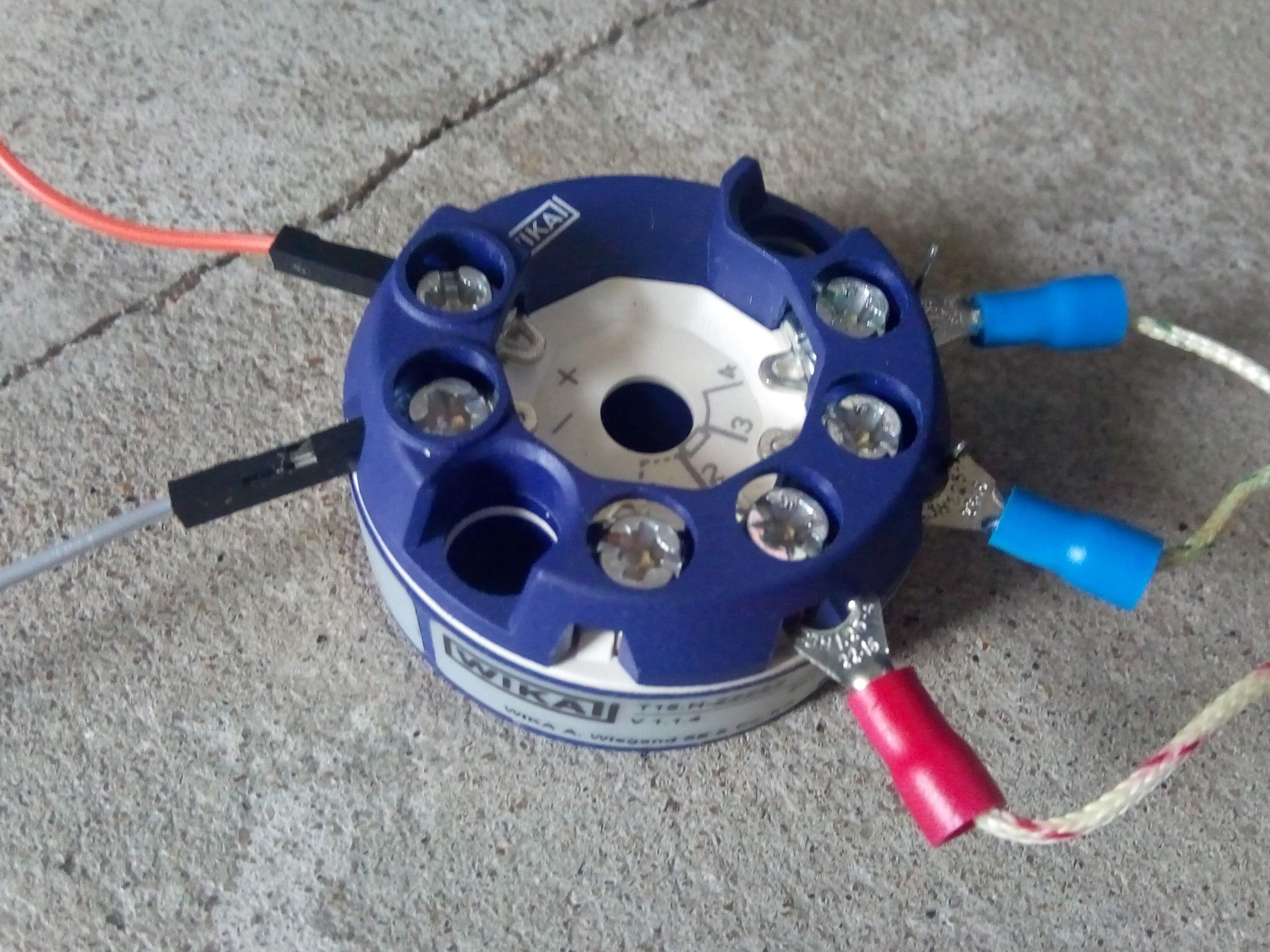
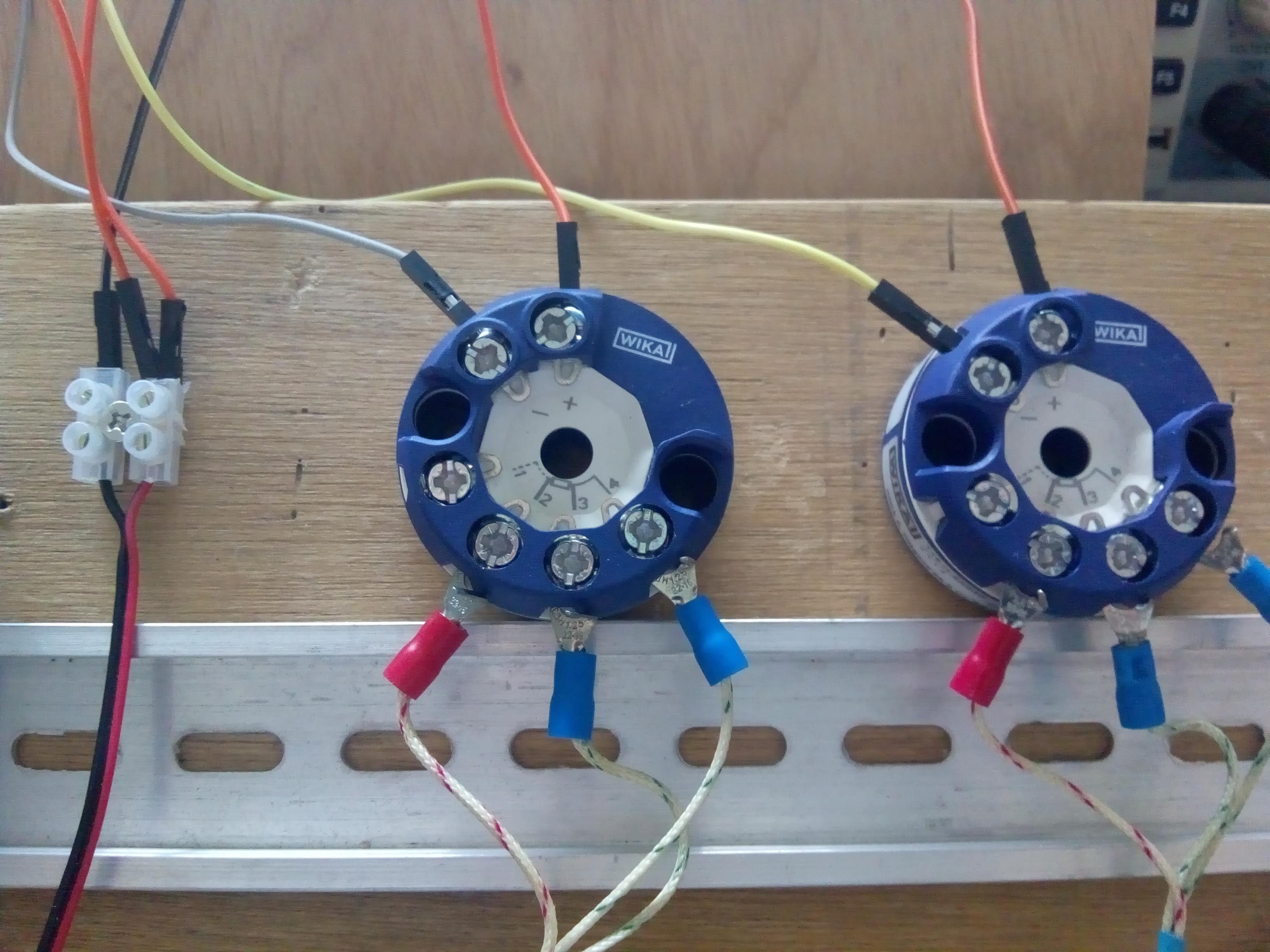
This is a close-up of our transmitter:
- PT100 connected with 3 wires, on terminals 2, 3, 4 as per WIKA datasheet. the sensor resistance is between terminal 2 and 3 (red and blue wires)
- Power is supplied via the + terminal, in our example we connect it to the V+ of the same 24Vdc PSU as the Industruino
- Signal is on the - terminal, and we connect this to the INDIO's analog input channel
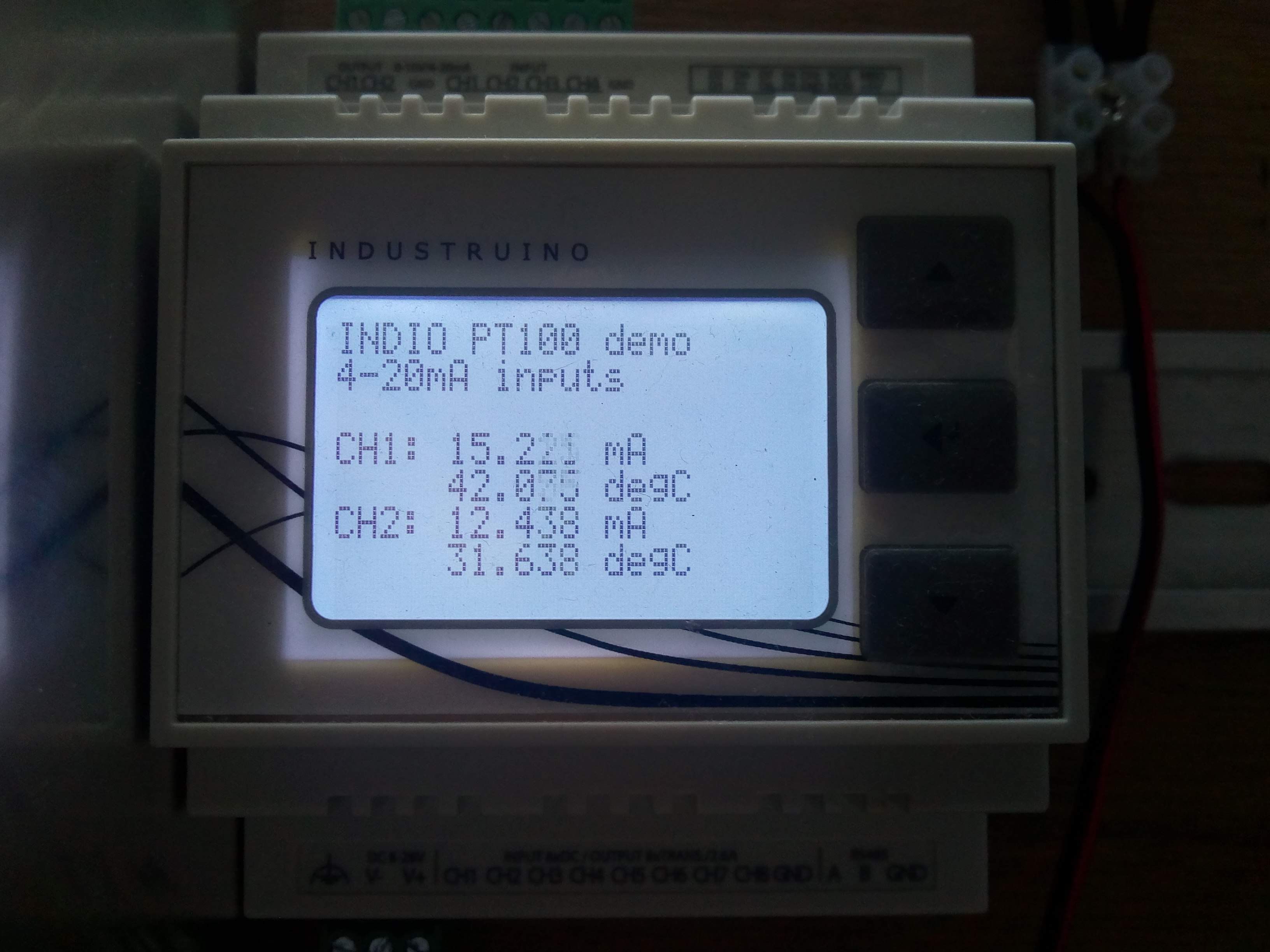
Finally, the code for this setup is very simple. Below sketch measures the 4-20mA signals on channels 1 and 2, with 12 bit resolution, and maps the current to a temperature range. This mapping will depend on your transmitter, below example maps 4mA to 0 degrees and 20mA to 60 degrees (constants defined at the top). Note that the Arduino map() function only takes integers, so we multiply the values by 1000 and then divide the result by 1000 to get decimal accuracy.
/*
 * DEMO for Industruino INDIO D21G analog input PT100 with 4-20mA transmitter
 * Tom Tobback, June 2020
 */

#include <Indio.h>
#include <Wire.h>

#include <UC1701.h>
static UC1701 lcd;

const int t_min = 0;
const int t_max = 60;

void setup()
{

  SerialUSB.begin(115200);
  lcd.begin();
  digitalWrite(26, HIGH);  // full backlight

  //  Indio.analogReadMode(1, V10); // Set Analog-In CH1 to 10V mode (0-10V).
  //  Indio.analogReadMode(2, V10_p); // Set Analog-In CH2 to % 10V mode (0-10V -> 0-100%).
  //  Indio.analogReadMode(3, mA); // Set Analog-In CH3 to mA mode (0-20mA).
  //  Indio.analogReadMode(4, mA_p); // Set Analog-In CH4 to % mA mode (4-20mA -> 0-100%)
  //  Indio.analogReadMode(4, V5); // Set Analog-In CH4 to 5V mode (2x gain enabled on ADC).
  //  Indio.analogReadMode(4, V5_p); // Set Analog-In CH4 to 5V mode (0-5V -> 0-100%).
  //  Indio.analogReadMode(4, V10_raw); // Set Analog-In CH4 to 10V mode and read raw ADC value (0-10V -> 0-4096).
  //  Indio.analogReadMode(4, mA_raw); // Set Analog-In CH4 to mA mode and read raw ADC value (0-20mA -> 0-4096).

  Indio.setADCResolution(12); // Set the ADC resolution. Choices are 12bit@240SPS, 14bit@60SPS, 16bit@15SPS and 18bit@3.75SPS.
  Indio.analogReadMode(1, mA);
  Indio.analogReadMode(2, mA);

  lcd.clear();
  lcd.print("INDIO PT100 demo");
  lcd.setCursor(0,1);
  lcd.print("4-20mA inputs");

}

void loop()
{

  float sensorVal1 = Indio.analogRead(1); //Read Analog-In CH1 (output depending on selected mode)
  float sensorVal2 = Indio.analogRead(2); //Read Analog-In CH1 (output depending on selected mode)
  // for mapping, multiply by 1000 to get decimal accuracy, because the mapping function only takes integers
  float mapped_T1 = map(sensorVal1 * 1000.0, 4000, 20000, t_min * 1000.0, t_max * 1000.0) / 1000.0;
  float mapped_T2 = map(sensorVal2 * 1000.0, 4000, 20000, t_min * 1000.0, t_max * 1000.0) / 1000.0;

  SerialUSB.print("CH1: "); //Print "CH" for human readability
  SerialUSB.print(sensorVal1, 3); //Print data
  SerialUSB.print("mA \t"); //Add some "  " space
  SerialUSB.print(mapped_T1, 3);
  SerialUSB.print("degC \t");

  SerialUSB.print("CH2:"); //Print "CH" for human readability
  SerialUSB.print(sensorVal2, 3); //Print data
  SerialUSB.print("mA  \t"); //Add some "  " space
  SerialUSB.print(mapped_T2, 3);
  SerialUSB.print("degC \t");

  SerialUSB.println();

  lcd.setCursor(0, 3);
  lcd.print("CH1: ");
  lcd.setCursor(30, 3);
  lcd.print(sensorVal1, 3);
  lcd.print(" mA  ");
  lcd.setCursor(30, 4);
  lcd.print(mapped_T1, 3);
  lcd.print(" degC  ");
  lcd.setCursor(0, 5);
  lcd.print("CH2: ");
  lcd.setCursor(30, 5);
  lcd.print(sensorVal2, 3);
  lcd.print(" mA  ");
  lcd.setCursor(30, 6);
  lcd.print(mapped_T2, 3);
  lcd.print(" degC  ");

  delay(100);
}