Lithium charge/discharge monitor
Lithium batteries are everywhere today, from speakers to cars. They require a rather specific charging regime, so charger ICs like the TP4056 are used to manage individual cells.
This project uses an Industruino PROTO to build a Lithium charger and discharger, with graphs on the LCD, and data logging over WiFi. It uses a TP4056 charger PCB, an INA219 voltage/current monitor, and an ESP8266 WiFi module.
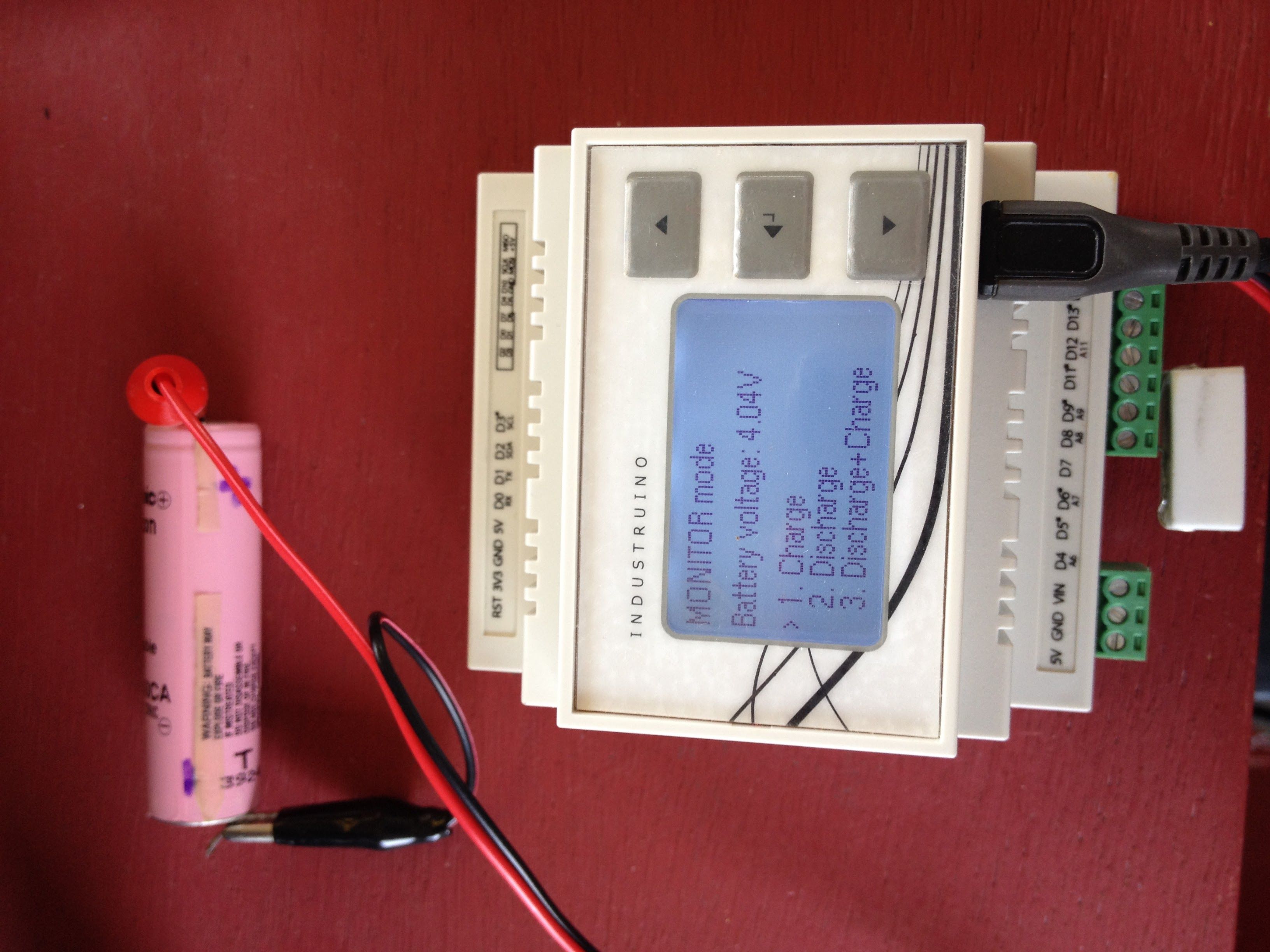
The MONITOR mode shows us the battery voltage, with no load, and allows us to choose from the menu using the buttons.
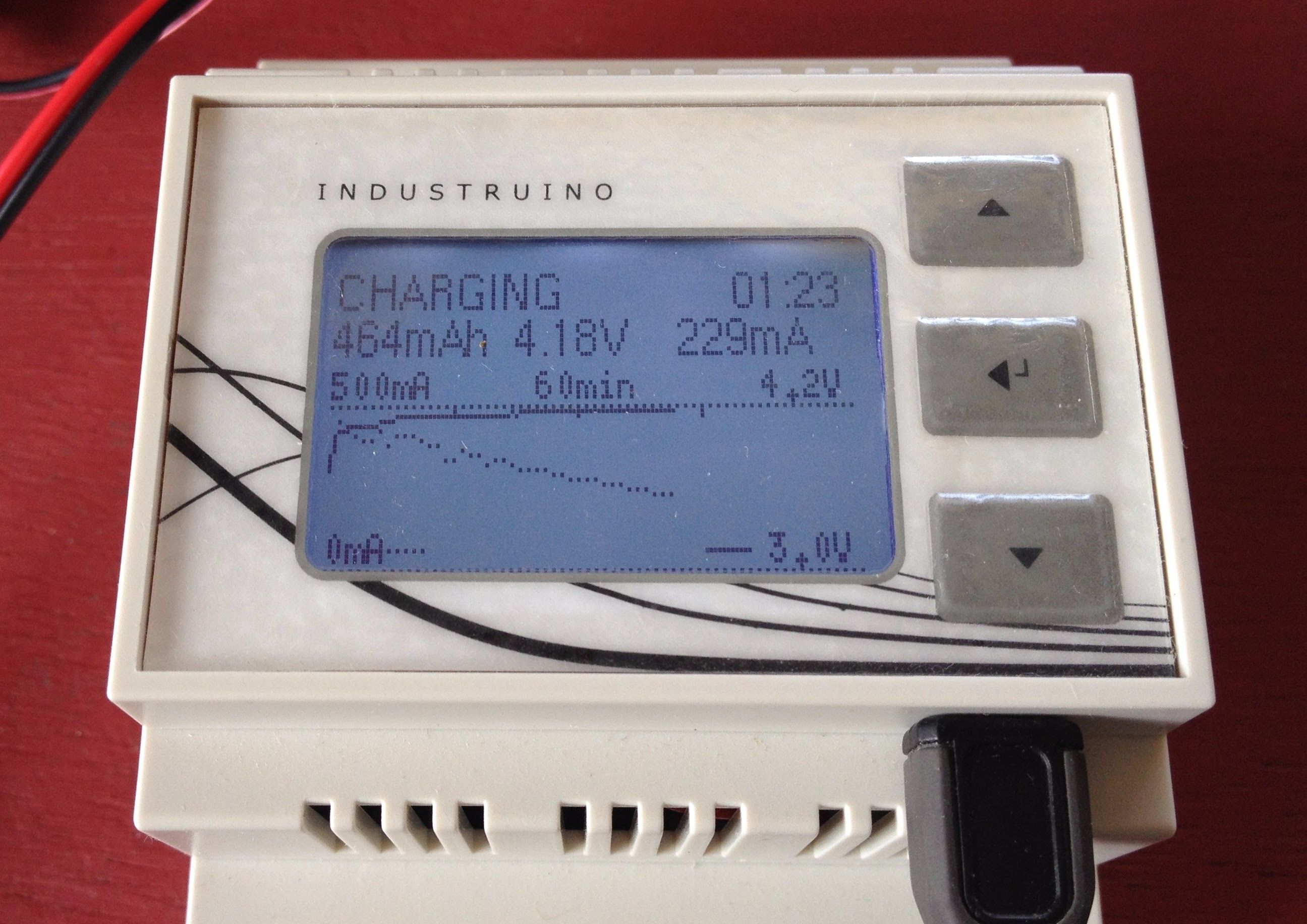
CHARGE: a P-type MOSFET switches the 5V USB power to the TP4056 charger module and the charging current passes through the INA219 (I2C to MCU). The display is refreshed every second, and every minute the data is sent over WiFi to a cloud server, emoncms.org
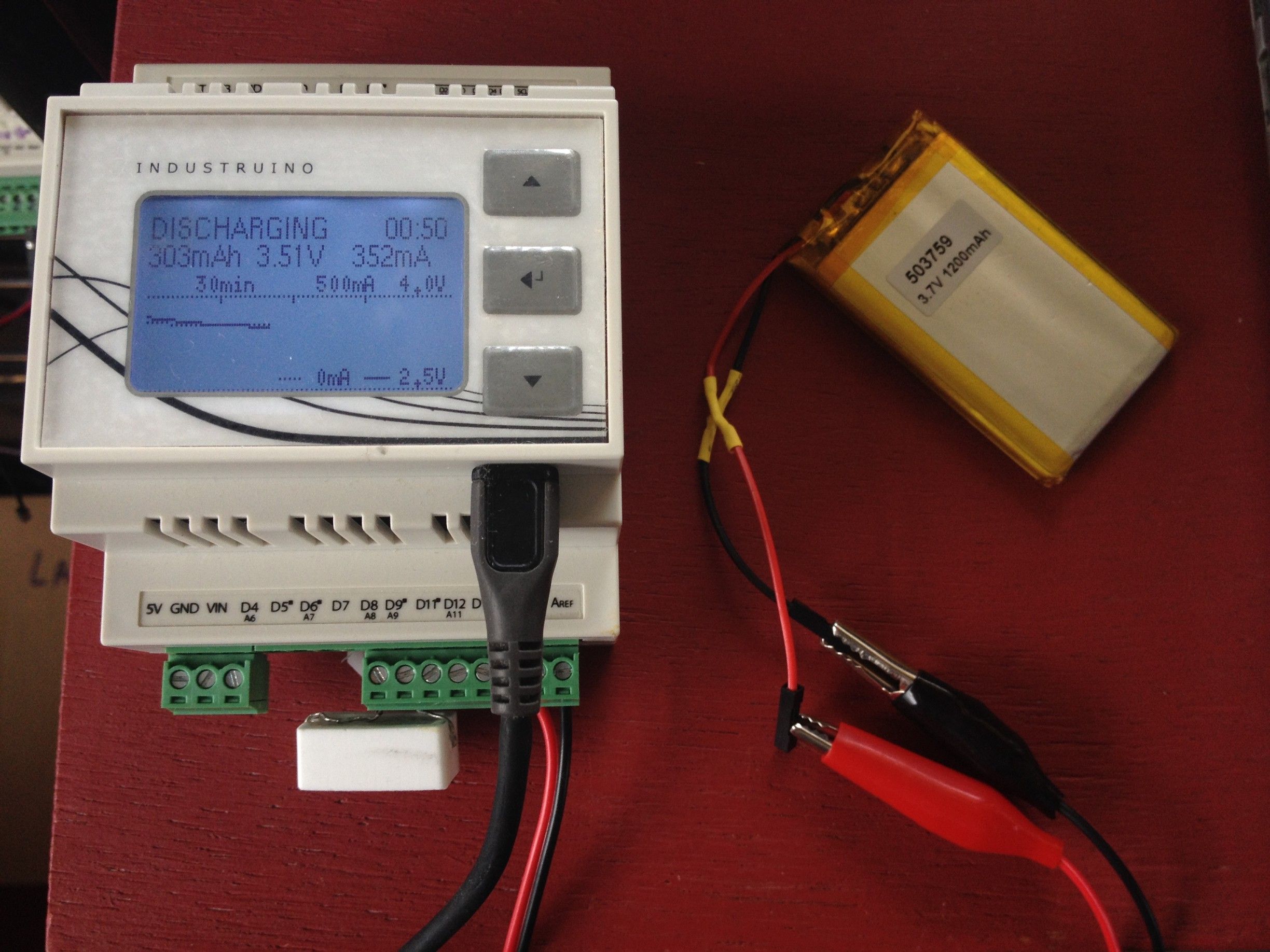
DISCHARGE: a N-type MOSFET switches on a resistive load on the battery. The resistor is mounted on the bottom green screw connectors as in the picture on the left (10ohm, 5W). The load is connected directly to the battery (and INA219), not using the 'OUT' terminals on the TP4056 PCB (with under voltage/over current protection) so the Industruino has to stop discharge at a specific voltage (e.g. 2.5V) and current (e.g. 500mA).
Advantages of the Industruino PROTO for this project:
- Built in LCD and membrane buttons, plug&play
- Screw connectors can be used for GPIO or easily reconfigured for external connections: in this case the battery and the load resistor
- Easy interface with MCU (I2C for INA219 and Hardware Serial for ESP8266)
- Plenty of prototyping area to add components inside the casing
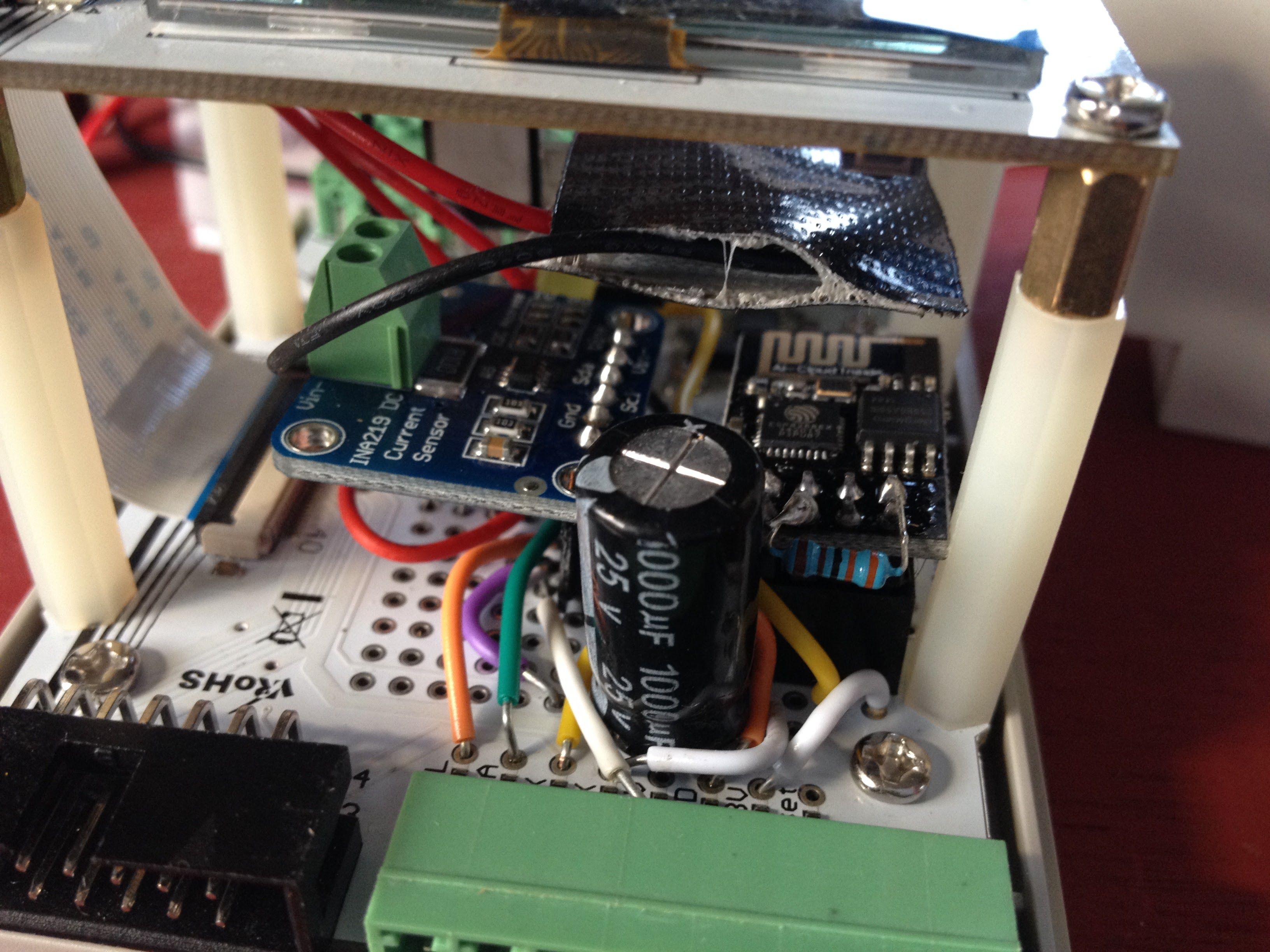
The picture above left shows the INA219 on the left and the ESP8266 on the right, with its a large decoupling capacitor.
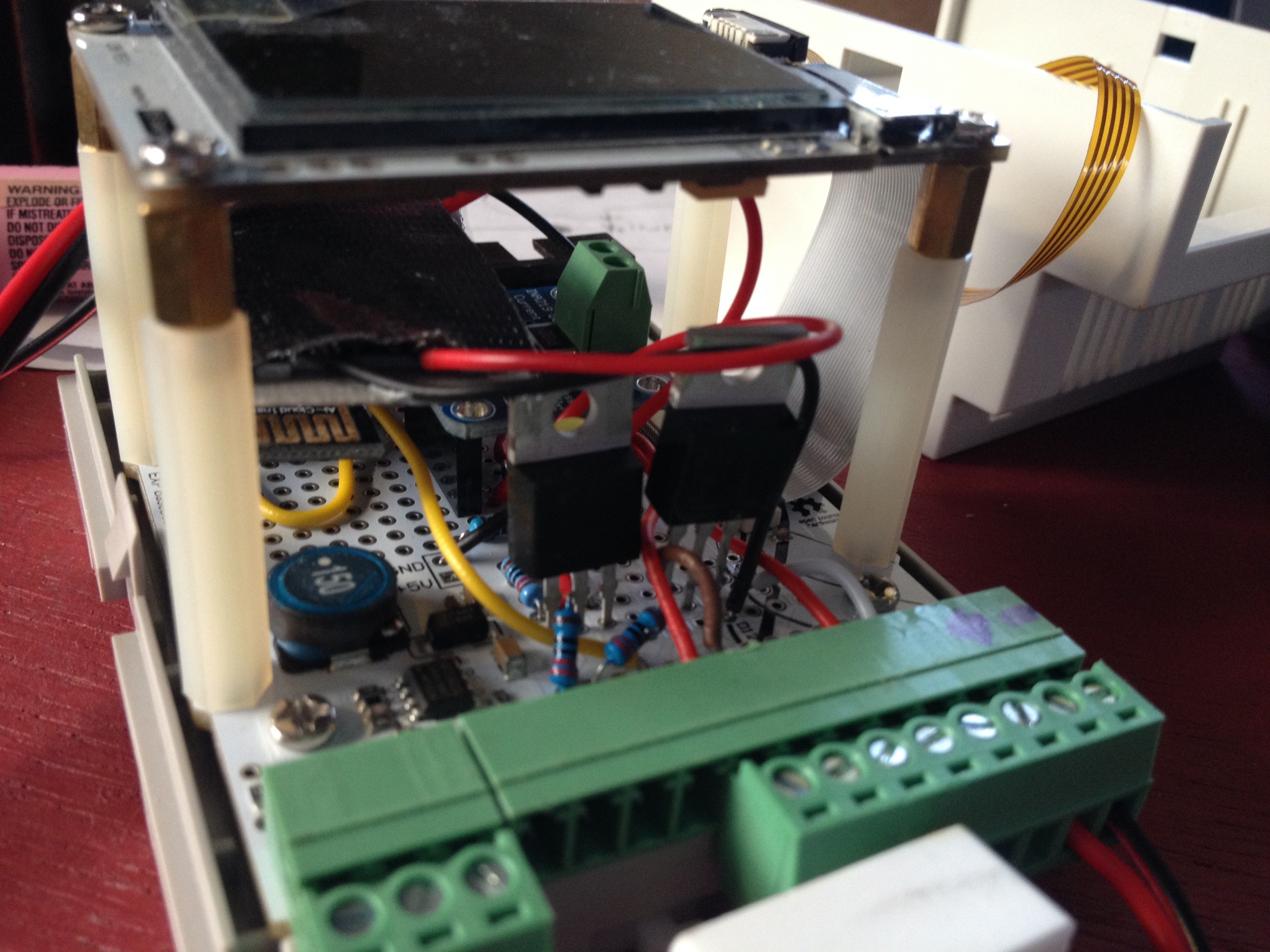
The picture on the right shows the 2 MOSFETs to switch the charging and discharging.
The battery wires are connected to 2 green screw terminals, after removing the 0ohm resistors to disconnect the terminals from the GPIO pins. In the same way the load resistor is connected to 2 green screw terminals.
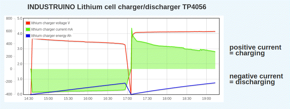
The LCD has 128 pixels horizontally, with one data point per minute, so the graph shows maximum 2 hours of data. It shows the elaptsed time in the upper right corner of the screen.
Dotted line for current (mA), full line for voltage (V).
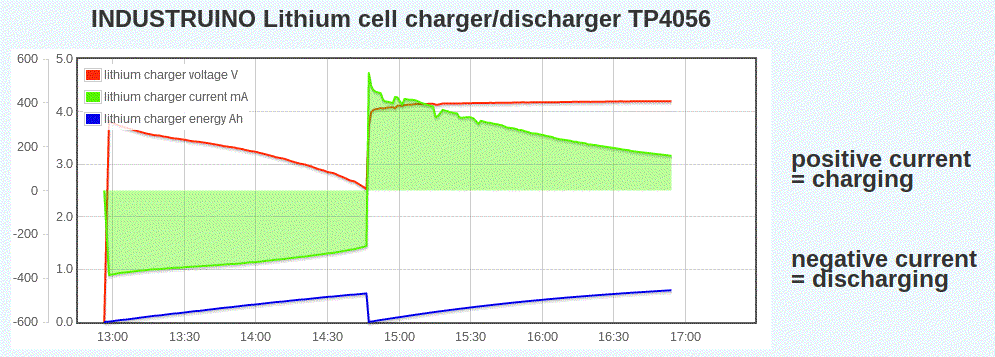
Below graph shows automated discharge+charge of a 1200mAh Lipo battery: very gradual voltage decline, then sudden drop around 3.3V after discharging around 750mAh. The charging is supposed to start with Constant Current, but the few batteries that i have tested rather show a linearly decreasing current, not as ideal as the CC/CV graphs reported here. This is probably due to the relatively high shunt resistor in the INA219: it is R100 = 100 mOhm. It seems Lithium batteries have an internal resistance in the order of 100s of mOhm so the shunt probably affects the charging cycle.