An Industruino customer asked us for help with implementing an industrial control system for disinfection of an air stream. We use the Industruino IND.I/O's digital outputs to control 3 relays (at Vin voltage), simulated in the above picture with 3 LEDs. The number of lights activated is determined by the analog reading of a velocity sensor (4-20mA), resulting in a level from 1 to 3, and a pathogen detector (0/5V) to override this. Also radiometer is read as analog input (4-20mA). The readings and calculated level are displayed on the Industruino LCD.
In the above picture, the analog readings (velocity, radiometer) are simulated by a potentiometer. The pathogen detection, an on/off signal at 0/5V also uses an analog input because the digital inputs require a Vin voltage to switch to high. The analog input channel is configured to read 0-10V so can easily detect the 5V high level.
The system also makes sure that each of the 3 sets of lights are used the same amount of time. The code keeps track of the runtime of each set of lights, and after a set interval switches to the least used set(s) of lights.
We also added a (internal ATmega hardware) watchdog timer to make sure the system does not get stuck.
All parameters displayed on the screen are also made available over Modbus TCP. We connected a standard Industruino Ethernet module to the IND.I/O, seen on the top right of above picture (without its DIN-rail casing). The Industruino is configured as the Modbus Slave, making registers available for reading by a Modbus Master. We simulated the Modbus Master with this tool on a Windows laptop.
We use the MgsModbus library available here. This library is easy to get working, just needs 2 points of attention:
- in MgsModbus.cpp: change ServerIp (line19) to IP of slave
- in MgsModbus.h: make sure line60 points to the Industruino version of the Ethernet library
It is relatively straight forward to start from the library Slave example and insert that code into your own sketch. First get the example Slave sketch to work by editing your network setting (lines10-12): e.g. ip: 192.168.1.99, gateway: 192.168.1.1, subnet: 255.255.255.0 and in the library file MgsModbus.cpp: set ServerIP: 192.168.1.99 (slave IP).
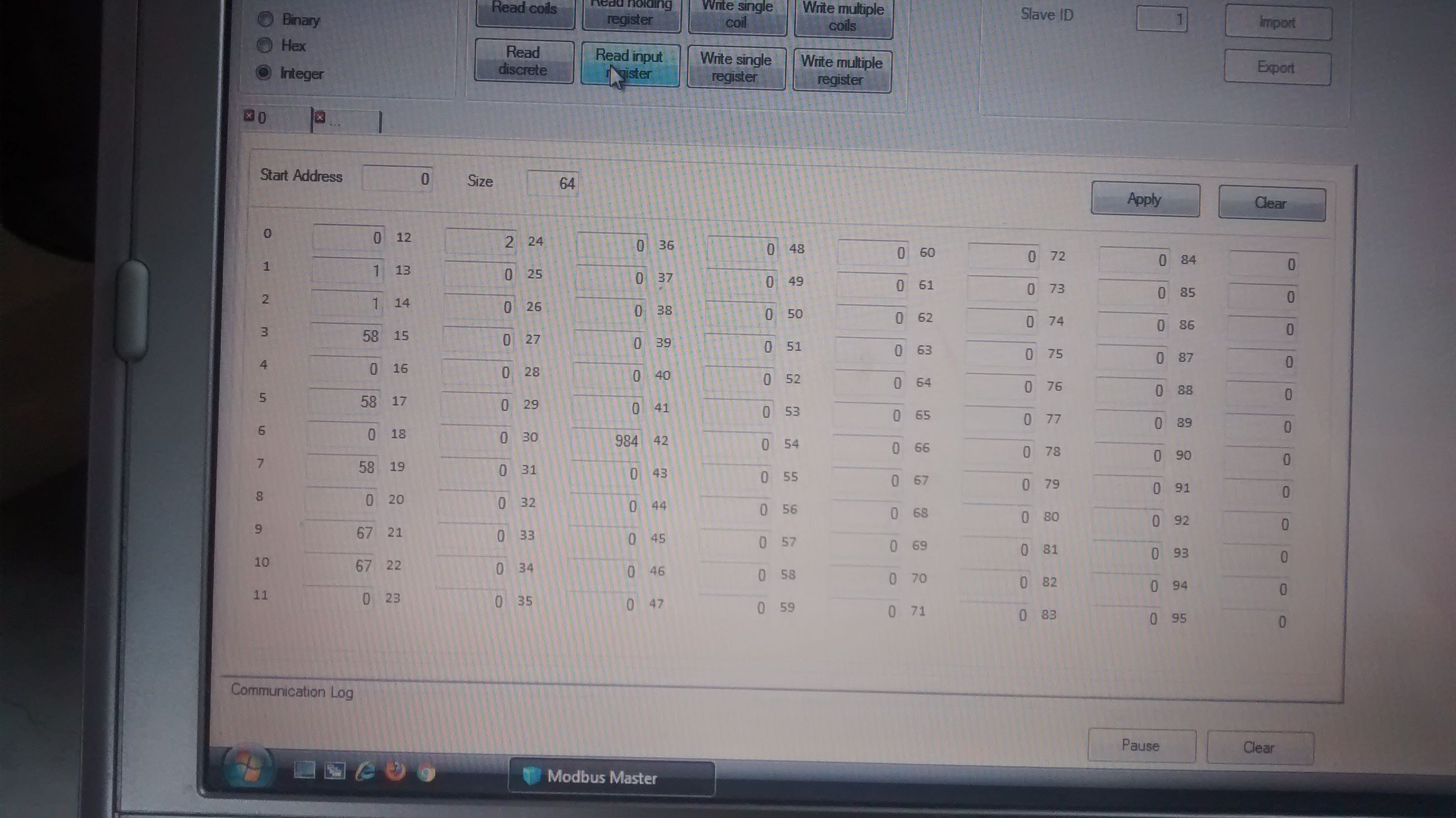
Above screenshot shows the Modbus Master simulator on a laptop connected to the same router as the Industruino Ethernet module. Connect to the Slave with the IP as configured above, and default port 502. Then click 'Read input registers'. In our case, it gives us 13 values (standard Modbus 16-bit integers), of which some are actually highInt/lowInt pairs of 32-bit integers we use for the runtime variables.
If you are interested in custom code for your Industruino projects, contact tom@industruino.com