Connecting the cheap ESP8266 WiFi module to an Industruino
The ESP8266 is a very popular WiFi SoC that can cost as little as US$3 in its simplest for, the ESP-01 package which we're using here. This is an 8-pin module with a PCB antenna, that comes with firmware allowing us to communicate with our MCU over a Serial connection, using AT commands.
Here we will show how to connect this WiFi module to the pins available on the Industruino's 14-pin IDC expansion port that is normally used to connect the Ethernet module. For both the PROTO and the IND.I/O the digital I/O pins on this IDC port are directly connected to the MCU.
The obvious choice is to use the MCU's extra hardware Serial, 'Serial1' on D0 and D1 for this purpose. This Serial1 is available on both the 32u4 and the 1286 MCU. However, on the IND.I/O baseboard, these 2 pins are connected to the RS485 port which also uses the Serial1. Unfortunately at this stage the only solution is to unsolder pin 5 on the ADUM1402 chip to disconnect D0 from the RS485. A good alternative is to use SoftwareSerial, see the example below. So to summarise:
- PROTO baseboard: can use hardware Serial1 (D0/D1) OR SoftwareSerial
- IND.I/O baseboard: should use SoftwareSerial (or unsolder 1 pin on the PCB if RS485 is not needed)
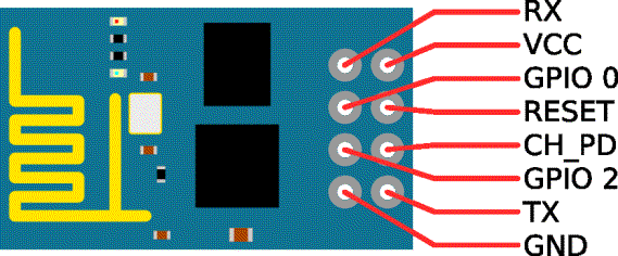
We only need to connect only 5 pins:
- Vcc should be 3.3V and it is important to make sure enough current can be supplied (up to 1A, see below)
- GND
- TX to RX on the MCU
- RX to TX on the MCU
- RST is the reset pin and should also be pulled high; here we will connect it to a MCU pin.
CH_PD should be pulled high, e.g. with a pull-up resistor.
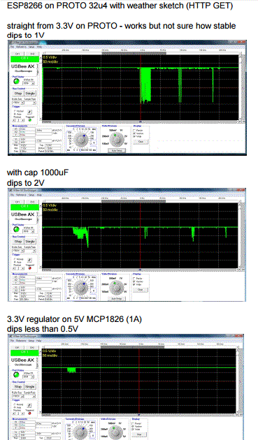
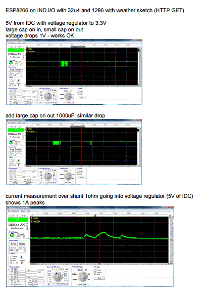
ESP8266 power supply
Hardware Serial
Hardware Serial is available on the IDC expansion port: D0 as RX and D1 as TX. They can be connected straight to the ESP module, D0 to its TX and D1 to its RX.
Software Serial
Software Serial needs a pin with PCINT for its RX: an interrupt needs to be triggered when receiving data. On the 32u4 topboard, we can use pin 8, 9, 10, 11 or the SPI pins 14, 15, 16, same as on the standard Arduino Leonardo. On the 1286 topboard the pins 8, 9, 10, 11 do not have PCINT, so we are limited to the SPI pins on the IDC connector, any one of them:
- D14 = MISO
- D15 = SCK
- D16 = MOSI
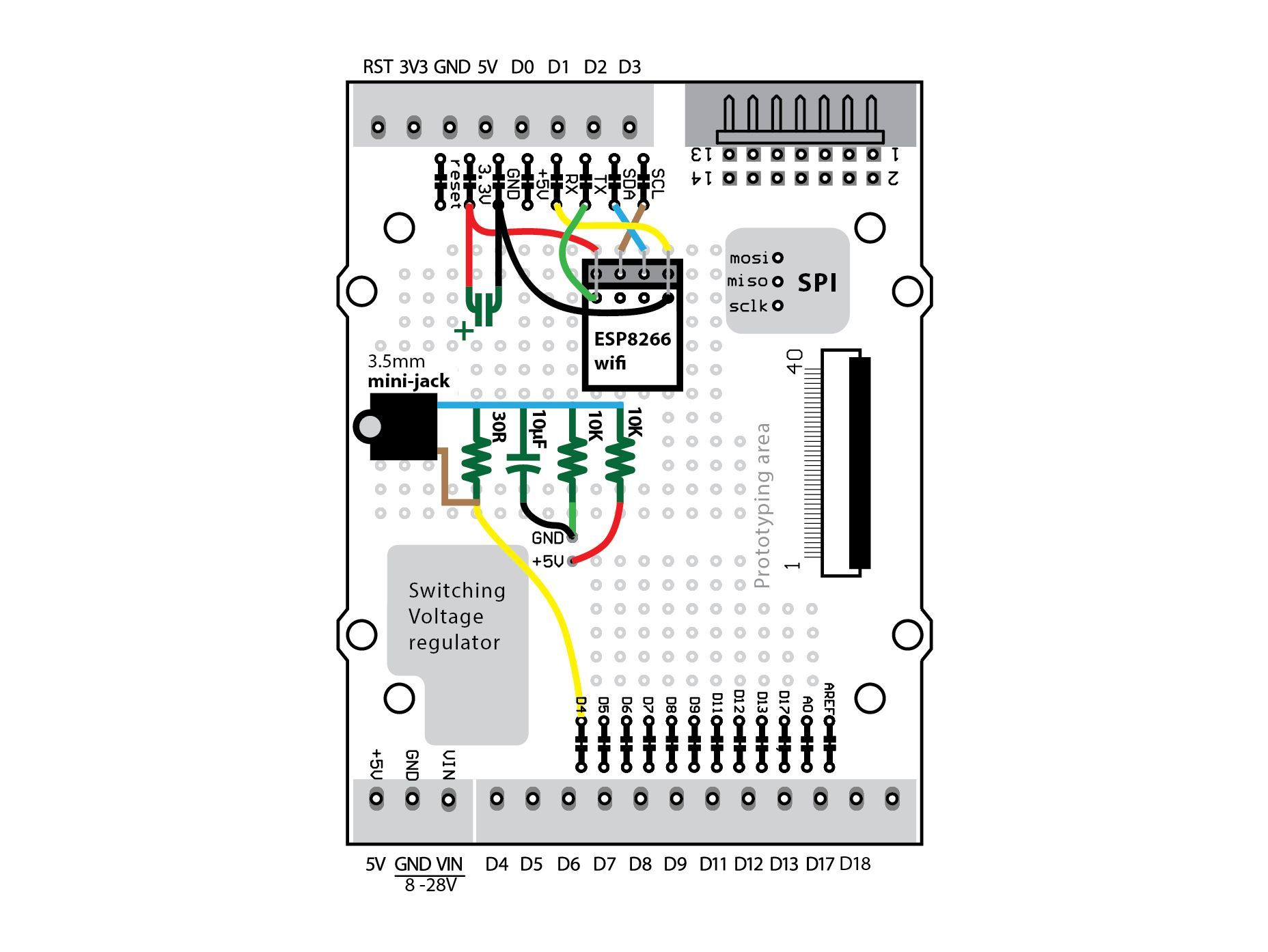
The diagram on the left show a possible integration of the ESP8266 on a PROTO baseboard, as used in the Power Meter project, using the Hardware Serial on D0/D1, and D3 for Reset (can be any digital pin). The Power-Down (CH_PD) is optional (here on D2), it can just be pull-up with a resistor. As far as our experience goes, the ESP8266 GPIO pins seem to be 5V tolerant.
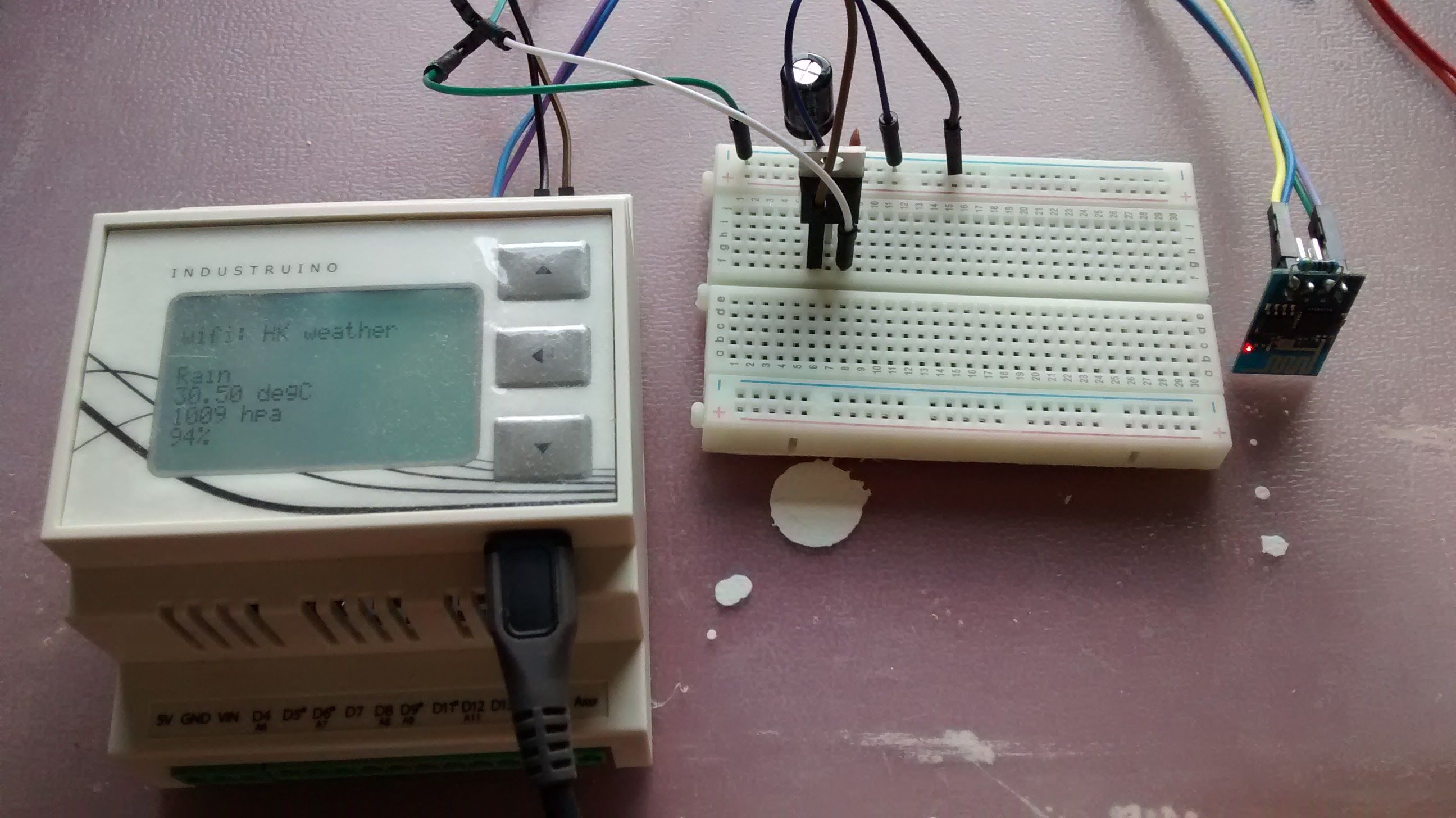
The example sketches below connect to a WiFi network and then send an HTTP GET request to a server, in this case http://openweathermap.org/ which has weather data. You need an API key to retrieve these data. The sketch then parses the reply to extract several data fields and display them on the LCD.
Example sketch with Hardware Serial
/*
* INDUSTRUINO proto/indio with ESP8266 on IDC expansion port using HARDWARE SERIAL
* D0 => TX on ESP
* D1 => RX on ESP
* D3 => RST on ESP
* GND to GND
* Vcc to 3.3V (straight on PROTO) or with voltage regulator for increased stability

* PROTO works with hardware SERIAL1
* IND.I/O does not work because of RS485: only works when unsoldering pin 5 on Adum1402 isolator
*/

#include <UC1701.h>
static UC1701 lcd;

// WIFI VARIABLES
#define SSID "xx"
#define PASS "xx"
#define DST_IP "192.241.169.168"

void setup() {

  pinMode(3, OUTPUT);    // ESP reset pin
  digitalWrite(3, HIGH);

  Serial.begin(9600);
  //  while (!Serial);
  Serial1.begin(9600);

  analogWrite(13, 0);
  lcd.begin();  //sets the resolution of the LCD screen
  lcd.clear();
  lcd.setCursor(1, 2);
  lcd.print("hello Industruino!");
  lcd.setCursor(1, 3);
  lcd.print("wifi: HK weather");
  lcd.setCursor(1, 4);
  lcd.print("ESP8266 on Serial1");
}

void loop() {
  checkWeather();
  delay(3000);
}

boolean checkWeather()
{
  Serial1.println("AT+RST");
  delay(500);

  if (Serial1.find("Ready"))
  {
    Serial.print(F("module is ready.."));
  }
  else
  {
    Serial.println(F("module has no response."));
    return false;
  }

  //connect to the wifi
  boolean connected = false;

  for (int i = 0; i < 5; i++)
  {
    if (connectWiFi())
    {
      connected = true;
      break;
    }
  }
  if (!connected) {
    Serial.println(F("tried 5 times to connect, hard reset"));
    digitalWrite(3, LOW);
    delay(200);
    digitalWrite(3, HIGH);
    return false;
  }
  delay(500);

  //set the single connection mode
  Serial1.println("AT+CIPMUX=0");
  delay(500);

  String cmd;
  cmd = "AT+CIPSTART=\"TCP\",\"";
  cmd += DST_IP;
  cmd += "\",80";
  Serial1.println(cmd);

  if (Serial1.find("Error")) return false;

  String action;
  action = "GET /data/2.5/weather?id=1818209&units=metric&APPID=xxxxxx";
  action += " HTTP/1.0\r\n\r\n";

  Serial1.print("AT+CIPSEND=");
  Serial1.println(action.length());

  if (Serial1.find(">"))
  {
    Serial.print(">");
  } else
  {
    Serial1.println("AT+CIPCLOSE");
    Serial.println(F("connect timeout"));
    return false;
  }

  Serial1.println(action);
  Serial.println(action);

  lcd.clear();
  lcd.setCursor(1, 1);
  lcd.print("wifi: HK weather");

  if (Serial1.find("main\":\""))
  {
    String main = Serial1.readStringUntil('"');
    Serial.print("found main: ");
    Serial.println(main);
    lcd.setCursor(1, 3);
    lcd.print(main);
  }
  if (Serial1.find("temp\":"))
  {
    float temp = Serial1.parseFloat();
    Serial.print("found temp: ");
    Serial.println(temp);
    lcd.setCursor(1, 4);
    lcd.print(temp);
    lcd.print(" degC");
  }
  if (Serial1.find("pressure\":"))
  {
    int pres = Serial1.parseInt();
    Serial.print("found pressure: ");
    Serial.println(pres);
    lcd.setCursor(1, 5);
    lcd.print(pres);
    lcd.print(" hpa");
  }
  if (Serial1.find("humidity\":"))
  {
    int hum = Serial1.parseInt();
    Serial.print("found humidity: ");
    Serial.println(hum);
    lcd.setCursor(1, 6);
    lcd.print(hum);
    lcd.print("%");
  }
}

boolean connectWiFi() {
  Serial1.println("AT+CWMODE=1");
  delay(1000);
  String cmd = "AT+CWJAP=\"";
  cmd += SSID;
  cmd += "\",\"";
  cmd += PASS;
  cmd += "\"";
  // Serial.println(cmd);
  Serial1.println(cmd);
  delay(5000);

  if (Serial1.find("OK")) {
    Serial.print(F("connected to wifi.."));
    return true;
  } else
  {
    Serial.println(F("cannot connect to wifi"));
    return false;
  }
}
Example sketch with Software Serial
#define _SS_MAX_RX_BUFF 256 // RX buffer size ***** CHANGED FROM 64 by TomT
/*
 * INDUSTRUINO proto/indio with ESP8266 on IDC expansion port
 * using SoftwareSerial, works on INDIO and PROTO
 * D14/MISO => TX on ESP (works on both 32u4 and 1286; on 32u4 you can also use D10)
 * D4 => RX on ESP
 * D5 => RST on ESP
 * GND to GND
 * Vcc to 3.3V (straight on PROTO) or with voltage regulator for increased stability
 *
// 32u4 can have for SoftwareSerial RX: 8,9,10,11,14,15,16 (because all have PCINT)
// 1286 can only use 14 miso, 15 sck, 16 mosi (no PCINT on others)
 */

#include <SoftwareSerial.h>                // need to update softwareserial.h to increase RX_buffer to 256 from 64
SoftwareSerial espSerial(14, 4); // RX, TX

#include <UC1701.h>
static UC1701 lcd;

// WIFI VARIABLES
#define SSID "xx"
#define PASS "xx"
#define DST_IP "192.241.169.168"

void setup() {

  pinMode(5, OUTPUT);    // ESP reset pin
  digitalWrite(5, LOW);  // ESP reset
  delay(200);
  digitalWrite(5, HIGH);

  Serial.begin(9600);
  //  while (!Serial);
  espSerial.begin(9600);

  analogWrite(13, 0);
  lcd.begin();  //sets the resolution of the LCD screen
  lcd.clear();
  lcd.setCursor(1, 2);
  lcd.print("hello Industruino!");
  lcd.setCursor(1, 3);
  lcd.print("wifi: HK weather");
  lcd.setCursor(1, 4);
  lcd.print("ESP8266 on softSerial");
}

void loop() {
  checkWeather();
  delay(3000);
}

boolean checkWeather()
{
  espSerial.println("AT+RST");
  delay(500);

//  while (espSerial.available()) {
//    Serial.write(espSerial.read());
//  }

  if (espSerial.find("Ready"))
  {
    Serial.print(F("module is ready.."));
  }
  else
  {
    Serial.println(F("module has no response."));
    return false;
  }

  //connect to the wifi
  boolean connected = false;

  for (int i = 0; i < 5; i++)
  {
    if (connectWiFi())
    {
      connected = true;
      break;
    }
  }
  if (!connected) {
    Serial.println(F("tried 5 times to connect, hard reset"));
    digitalWrite(5, LOW);
    delay(200);
    digitalWrite(5, HIGH);
    return false;
  }
  delay(500);

  //set the single connection mode
  espSerial.println("AT+CIPMUX=0");
  delay(500);

  String cmd;
  cmd = "AT+CIPSTART=\"TCP\",\"";
  cmd += DST_IP;
  cmd += "\",80";
  espSerial.println(cmd);

  if (espSerial.find("Error")) return false;

  String action;
  action = "GET /data/2.5/weather?id=1818209&units=metric&APPID=xxx";
  action += " HTTP/1.0\r\n\r\n";

  espSerial.print("AT+CIPSEND=");
  espSerial.println(action.length());

  if (espSerial.find(">"))
  {
    Serial.print(">");
  } else
  {
    espSerial.println("AT+CIPCLOSE");
    Serial.println(F("connect timeout"));
    return false;
  }

  espSerial.println(action);
  Serial.println(action);

  lcd.clear();
  lcd.setCursor(1, 1);
  lcd.print("wifi: HK weather");

  if (espSerial.find("main\":\""))
  {
    String main = espSerial.readStringUntil('"');
    Serial.print("found main: ");
    Serial.println(main);
    lcd.setCursor(1, 3);
    lcd.print(main);
  }
  if (espSerial.find("temp\":"))
  {
    float temp = espSerial.parseFloat();
    Serial.print("found temp: ");
    Serial.println(temp);
    lcd.setCursor(1, 4);
    lcd.print(temp);
    lcd.print(" degC");
  }
  if (espSerial.find("pressure\":"))
  {
    int pres = espSerial.parseInt();
    Serial.print("found pressure: ");
    Serial.println(pres);
    lcd.setCursor(1, 5);
    lcd.print(pres);
    lcd.print(" hpa");
  }
  if (espSerial.find("humidity\":"))
  {
    int hum = espSerial.parseInt();
    Serial.print("found humidity: ");
    Serial.println(hum);
    lcd.setCursor(1, 6);
    lcd.print(hum);
    lcd.print("%");
  }
  while (espSerial.available()) {   // flush serial input
    espSerial.read();
  }
}

boolean connectWiFi() {
  espSerial.println("AT+CWMODE=1");
  delay(1000);
  String cmd = "AT+CWJAP=\"";
  cmd += SSID;
  cmd += "\",\"";
  cmd += PASS;
  cmd += "\"";
  // Serial.println(cmd);
  espSerial.println(cmd);
  delay(5000);

  if (espSerial.find("OK")) {
    Serial.print(F("connected to wifi.."));
    return true;
  } else
  {
    Serial.println(F("cannot connect to wifi"));
    return false;
  }
}