Using the sample library as in the Modbus RTU Master post, SimpleModbusMaster and SimpleModbusSlave (versions V2rev2 and V10 respectively) we can establish communication over RS485 between 2 or more IND.I/Os, with one acting as the Master and the other one(s) as the Slave(s). This is one way of expanding the Industruino's number of I/O pins.
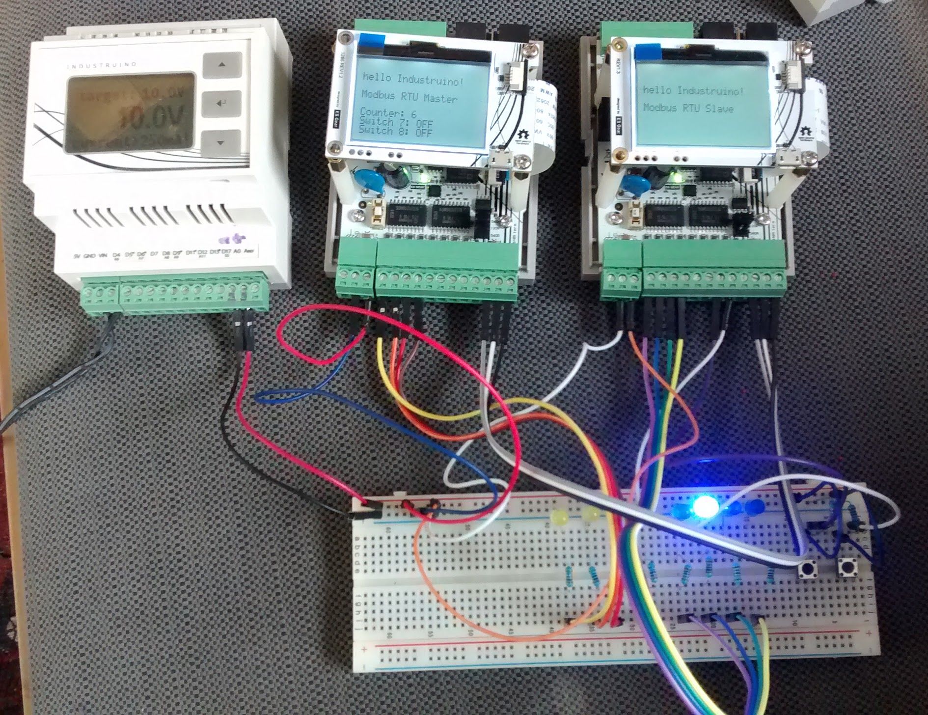
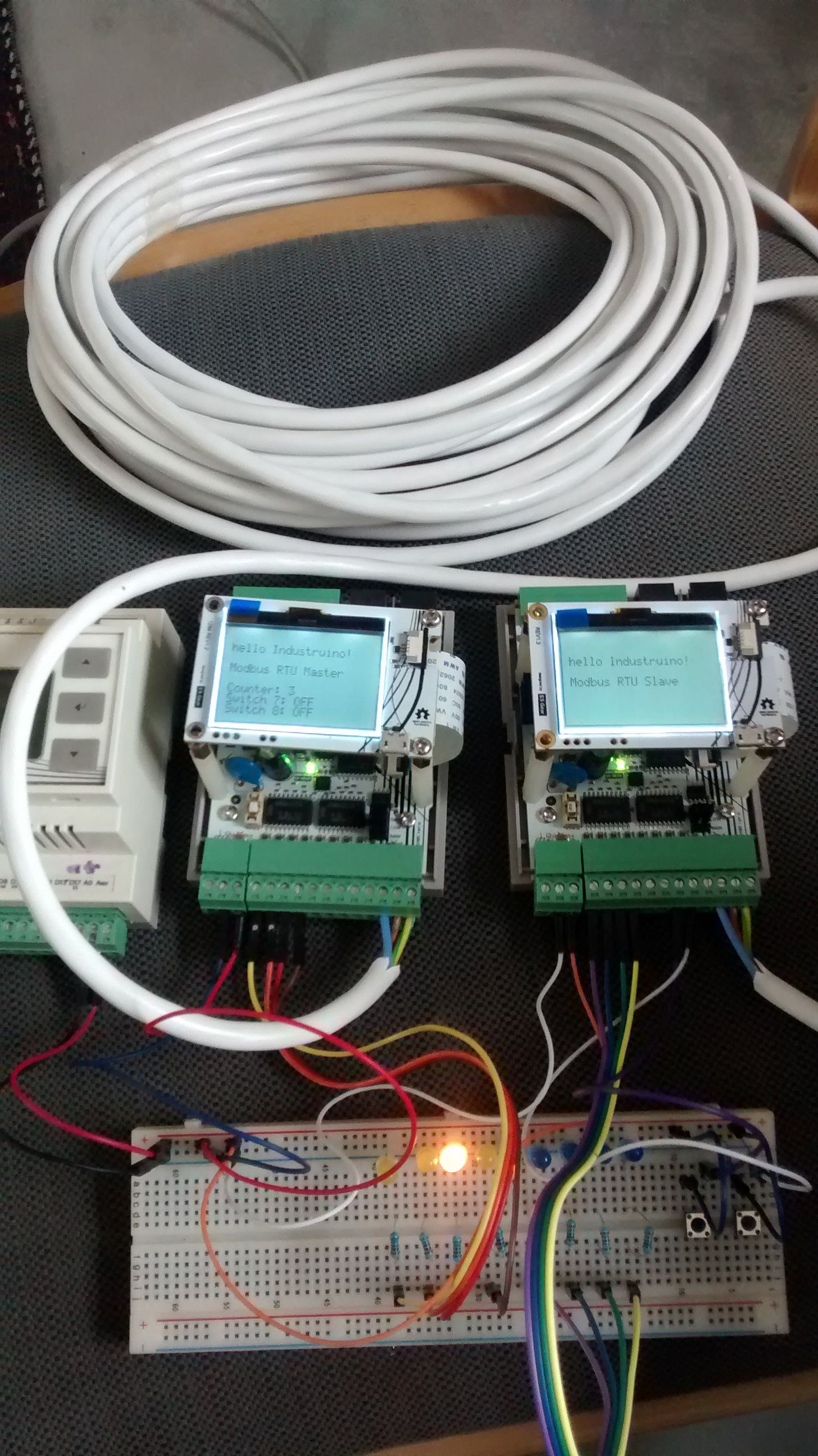
We tested this with 2 IND.I/O kits, as shown on the left.
RS485 connections are simple: A to A, B to B,and GND to GND
(grey - white -black wires in the picture)
To keep it simple, let’s only consider the Modbus HOLDING REGISTERS, which allow:
-
Reading data from the Slave with Modbus function 3: READ_HOLDING_REGISTERS
-
writing to the Slave with Modbus function 16: PRESET_MULTIPLE_REGISTERS
This allows us to read from/write to the Slave. The registers use 16-bit integers so can be used for digital as well as analog data values.
See below for example sketches.
The Master is sending out periodic requests with these 2 functions; the Slave is listening for requests, both using modbus_update() function in the sketch loop. Main parameters:
-
Slave ID (example: 2)
-
Baud rate (use 9600 on the Industruino D21G, higher rates may not work)
-
Name of the Serial port (Serial on IND.I/O)
-
RS485 Tx enable pin (9 on IND.I/O)
-
Additional Master parameters: timeout, polling, retry_count
Note 1: Latency
Modbus RTU does not give instant communication; there is a minimum latency of e.g. 20 milliseconds on the Master side (see this explanation) and also the Slave needs time to go back to Idle state, as explained in the SimpleModbusMasterManual in above link:
The fifth parameter, the polling delay, is sometimes the most confusing to explain to users. It is the resting period between requests from the master to allow a slave to enter its idle state. This is because a slave also runs on an FSM and can only start responding to a request once the idle state is reached. Some quick acting slaves will revert to the idle state within 10ms but the usual slave will take around 100ms – 200ms.
Experiments show that with a baud rate of 115200, the modbus_update() function on the Slave takes around 15-20ms (only when a request is received), and around 10ms on the Master.
Note 2: Using delay();
The SimpleModbusMasterManual recommends not using delay() of more than 100 msec:
Using delays longer than 100ms will affect the FSM negatively. It is not good practice to use large delays when coding. Rather use millis() to form some sort of crude multi-tasking.
See Master sketch example.
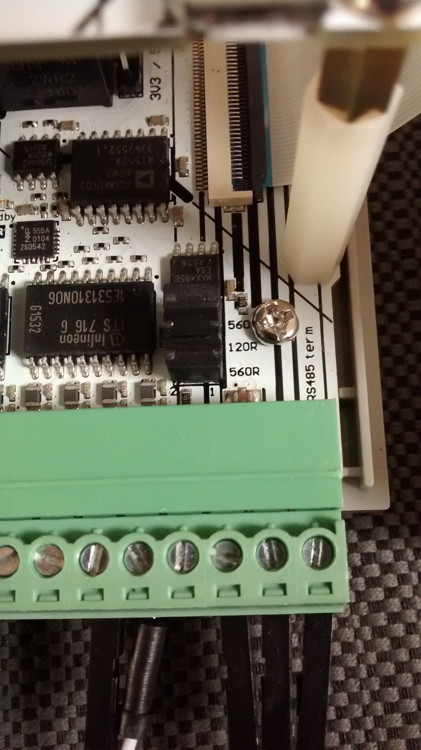
Note 3: RS485 termination resistors
The SimpleModbusMasterManual recommends the following termination resistor setup:
MASTER:
-
120R between A and B IND.I/O: leave middle jumper
-
510R pull-up on D+=A IND.I/O: leave top jumper
-
510R pull-down on D-=B IND.I/O: leave bottom jumper
-
100R in series on GND IND.I/O no resistor, add external if needed
SLAVE:
-
120R between A and B IND.I/O: leave middle jumper
-
100R in series on GND IND.I/O no resistor, add external if needed
-
no pull-up or pull-down IND.I/O: remove top and bottom jumpers
Example of Modbus RTU communication between 2 IND.I/Os, Master and Slave
This example has the following setup:
Master
-
IND.I/O, Vin = 10V
-
4 LEDs connected to digital CH1-4 (yellow)
-
3 wires of RS485
Slave
-
IND.I/O, Vin = 10V
-
4 LEDs connected to digital CH1-4 (blue)
-
2 push buttons connected to digital CH7-8
-
3 wires of RS485
Functionality to illustrate I/O over Modbus RTU:
-
the Master controls the 4+4 LEDs to switch ON one at a time, one by one
-
the Master uses direct Indio.digitalWrite commands for the 4 first LEDs
-
the Master uses Modbus registers [0-3] to control the 4 LEDs on the Slave
-
the Master polls registers [6-7] for the status of 2 push buttons on the Slave
-
the Slave updates its 4 LEDs with registers [0-3]
-
the Slave updates registers [6-7] with the status of the 2 push buttons
The video shows the LEDs blinking one by one, on the Master and Slave, and the status of the buttons connected to the Slave, on the Master LCD screen.
Modbus RTU Master example sketch
tested in Arduino IDE 1.8.2 with IND.I/O D21G (and IDE 1.6.5 with 1286 topboard)
#include <Wire.h>
#include <Indio.h>
#include <SimpleModbusMaster.h>
#include <UC1701.h>
static UC1701 lcd;

/*
  this example uses holding registers:
  [0-3] sends 4 registers (int) to the slave: status of 4 LEDs = digital outputs of the slave
  [6-7] reads 2 registers (int) from the slave: status of 2 PUSH BUTTONS = digital inputs of the slave
  actually we read 4 registers but only 2 are connected to buttons
*/

//////////////////// Port information ///////////////////
#define baud 9600  // use 9600 on D21G
#define timeout 1000
#define polling 20 // the scan rate, standard was 200
#define retry_count 10

// used to toggle the receive/transmit pin on the driver
#define TxEnablePin 9                                                           // INDUSTRUINO RS485
#define SlaveID 2

// The total amount of available memory on the master to store data
#define TOTAL_NO_OF_REGISTERS 8                                          // e.g. INDIO digital I/O

// This is the easiest way to create new packets
// Add as many as you want. TOTAL_NO_OF_PACKETS
// is automatically updated.
enum
{
  PACKET1,                                          // set 4 registers
  PACKET2,                                          // read 4 registers
  TOTAL_NO_OF_PACKETS // leave this last entry
};

// Create an array of Packets to be configured
Packet packets[TOTAL_NO_OF_PACKETS];

// Masters register array
unsigned int regs[TOTAL_NO_OF_REGISTERS];
unsigned long previousMillis;
int counter = 0;

void setup()
{


  lcd.begin();
  lcd.clear();
  lcd.setCursor(1, 1);
  lcd.print("hello Industruino!");
  lcd.setCursor(1, 3);
  lcd.print("Modbus RTU Master");

  analogWrite(26, 100);  // LCD backlight

  Indio.digitalMode(1, OUTPUT);
  Indio.digitalMode(2, OUTPUT);
  Indio.digitalMode(3, OUTPUT);
  Indio.digitalMode(4, OUTPUT);

  // Initialize each packet: packet, slave-id, function, start of slave index, number of regs, start of master index
  // set 4 registers
  // read 4 registers

  modbus_construct(&packets[PACKET1], SlaveID, PRESET_MULTIPLE_REGISTERS, 0, 4, 0);
  modbus_construct(&packets[PACKET2], SlaveID, READ_HOLDING_REGISTERS, 4, 4, 4);

  // Initialize the Modbus Finite State Machine
  modbus_configure(&Serial, baud, SERIAL_8N2, timeout, polling, retry_count, TxEnablePin, packets, TOTAL_NO_OF_PACKETS, regs);
  // Serial = INDUSTRUINO RS485  -- Serial1 on 32u4/1286
}

void loop()
{
//  unsigned long moment = millis();
  modbus_update();                          // send Master request to Slave, as defined above
//  Serial.println(millis()-moment);
  // frequency is limited by polling parameter

  // the library manual suggests not using long delays but an interval instead
  // the below section updates a counter after an interval,
  // and switches ON one LED of 8: 4 on the Master and 4 on the Slave
  // first switch all OFF
  // then if counter points to first half, switch ON one on Master
  // if counter points to second half, switch ON one on Slave

  if (millis() - previousMillis > 500) {
    counter++;
    lcd.setCursor(1, 5);
    lcd.print("Counter: ");
    lcd.print(counter % 8 + 1);

    for (int u = 0; u < 4; u++) {       // set all to 0 on Master
      Indio.digitalWrite(u + 1, LOW);
    }
    for (int u = 0; u < 4; u++) {       // set [0-3] to 0 on Slave
      regs[u] = 0;
    }
    if (counter % 8 < 4) {              // if counter at first 4
      Indio.digitalWrite(counter % 8 + 1, HIGH);  // set 1 on Master
    }
    else {
      regs[counter % 8 - 4] = 1;         // set one of [0-3] to 1 on Slave
    }
    previousMillis = millis();
  }

  // this section prints the status of the 2 switch registers on the Slave

  lcd.setCursor(1, 6);
  if (regs[6]) lcd.print("Switch 7: ON ");    // print status of switch on Slave
  else lcd.print("Switch 7: OFF");
  lcd.setCursor(1, 7);
  if (regs[7]) lcd.print("Switch 8: ON ");    // print status of switch on Slave
  else lcd.print("Switch 8: OFF");
}
Modbus RTU Slave example sketch
#include <Wire.h>
#include <Indio.h>
#include <SimpleModbusSlave.h>
#include <UC1701.h>
static UC1701 lcd;

/*
   this example receives 4 registers from the master [0-3]
   and sets 4 registers [4-7]

   SimpleModbusSlaveV10 supports function 3, 6 & 16.

   function 3: READ_HOLDING_REGISTERS    **** this example uses this function [4-7]
   function 6: PRESET_SINGLE_REGISTER
   function 16: PRESET_MULTIPLE_REGISTERS **** this example uses this function [0-3]

   The modbus_update() method updates the holdingRegs register array and checks
   communication.

   Note:
   The Arduino serial ring buffer is 64 bytes or 32 registers.
   Most of the time you will connect the arduino to a master via serial
   using a MAX485 or similar.

   In a function 3 request the master will attempt to read from your
   slave and since 5 bytes is already used for ID, FUNCTION, NO OF BYTES
   and two BYTES CRC the master can only request 58 bytes or 29 registers.

   In a function 16 request the master will attempt to write to your
   slave and since a 9 bytes is already used for ID, FUNCTION, ADDRESS,
   NO OF REGISTERS, NO OF BYTES and two BYTES CRC the master can only write
   54 bytes or 27 registers.

   Using a USB to Serial converter the maximum bytes you can send is
   limited to its internal buffer which differs between manufactures.
*/

// used to toggle the receive/transmit pin on the driver
#define TxEnablePin 9                                                           // INDUSTRUINO RS485

#define   baud 9600   // use 9600 on D21G
#define   SlaveID 2
#define   HOLDING_REGS_SIZE 8

// Using the enum instruction allows for an easy method for adding and
// removing registers. Doing it this way saves you #defining the size
// of your slaves register array each time you want to add more registers
// and at a glimpse informs you of your slaves register layout.

//////////////// registers of your slave ///////////////////
/*
enum
{
  // just add or remove registers and your good to go...
  // The first register starts at address 0

  HOLDING_REGS_SIZE // leave this one
  // total number of registers for function 3 and 16 share the same register array
  // i.e. the same address space
};
*/

unsigned int holdingRegs[HOLDING_REGS_SIZE]; // function 3 and 16 register array
////////////////////////////////////////////////////////////

void setup()
{

  lcd.begin();
  lcd.clear();
  lcd.setCursor(1, 2);
  lcd.print("hello Industruino!");
  lcd.setCursor(1, 4);
  lcd.print("Modbus RTU Slave");

  analogWrite(26, 100);  // LCD backlight

  Indio.digitalMode(1, OUTPUT);
  Indio.digitalMode(2, OUTPUT);
  Indio.digitalMode(3, OUTPUT);
  Indio.digitalMode(4, OUTPUT);

  Indio.digitalMode(7, INPUT);
  Indio.digitalMode(8, INPUT);

  /* parameters(HardwareSerial* SerialPort,
                long baudrate,
      unsigned char byteFormat,
                unsigned char ID,
                unsigned char transmit enable pin,
                unsigned int holding registers size,
                unsigned int* holding register array)
  */

  /* Valid modbus byte formats are:
     SERIAL_8N2: 1 start bit, 8 data bits, 2 stop bits
     SERIAL_8E1: 1 start bit, 8 data bits, 1 Even parity bit, 1 stop bit
     SERIAL_8O1: 1 start bit, 8 data bits, 1 Odd parity bit, 1 stop bit

     You can obviously use SERIAL_8N1 but this does not adhere to the
     Modbus specifications. That said, I have tested the SERIAL_8N1 option
     on various commercial masters and slaves that were suppose to adhere
     to this specification and was always able to communicate... Go figure.

     These byte formats are already defined in the Arduino global name space.
  */

  modbus_configure(&Serial, baud, SERIAL_8N2, SlaveID, TxEnablePin, HOLDING_REGS_SIZE, holdingRegs);

  // modbus_update_comms(baud, byteFormat, id) is not needed but allows for easy update of the
  // port variables and slave id dynamically in any function.
  modbus_update_comms(baud, SERIAL_8N2, SlaveID);

}

void loop()
{
  // modbus_update() is the only method used in loop(). It returns the total error
  // count since the slave started. You don't have to use it but it's useful
  // for fault finding by the modbus master.
  // the library manual suggests not using long delays but an interval instead
//  unsigned long moment = millis();
  modbus_update();
//  unsigned long interval = millis()-moment;
//  if (interval > 0) Serial.println(interval);

  holdingRegs[6] = Indio.digitalRead(7);    // set register according to button on Slave
  holdingRegs[7] = Indio.digitalRead(8);    // set register according to button on Slave

  for (int u = 0; u < 4; u++) {
    Indio.digitalWrite(u + 1, holdingRegs[u]);  // switch on LED according to Master request
  }

  /* Note:
     The use of the enum instruction is not needed. You could set a maximum allowable
     size for holdinRegs[] by defining HOLDING_REGS_SIZE using a constant and then access
     holdingRegs[] by "Index" addressing.
     I.e.
     holdingRegs[0] = analogRead(A0);
     analogWrite(LED, holdingRegs[1]/4);
  */

}