IND.I/O analog calibration procedure
The calibration data is stored in the Indio library file: Indio.cpp (approximately lines 41 to 75). It consists of 4 blocks:
- ADC voltage 0-10V
- ADC current 4-20mA
- DAC voltage 0-10V
- DAC current 4-20mA
The library is preloaded with default calibration data, but characteristics are board specific thus reading with default calibration data might be off. You are advised to update the calibration arrays in your own Indio.cpp file. You can update all 4 modes above, or only the mode that you will use. Instructions are also available on our Github pages.
To perform this calibration, you will need a digital multimeter, a variable voltage supply, and ideally a variable current supply but this you can also obtain with a simple resistor.
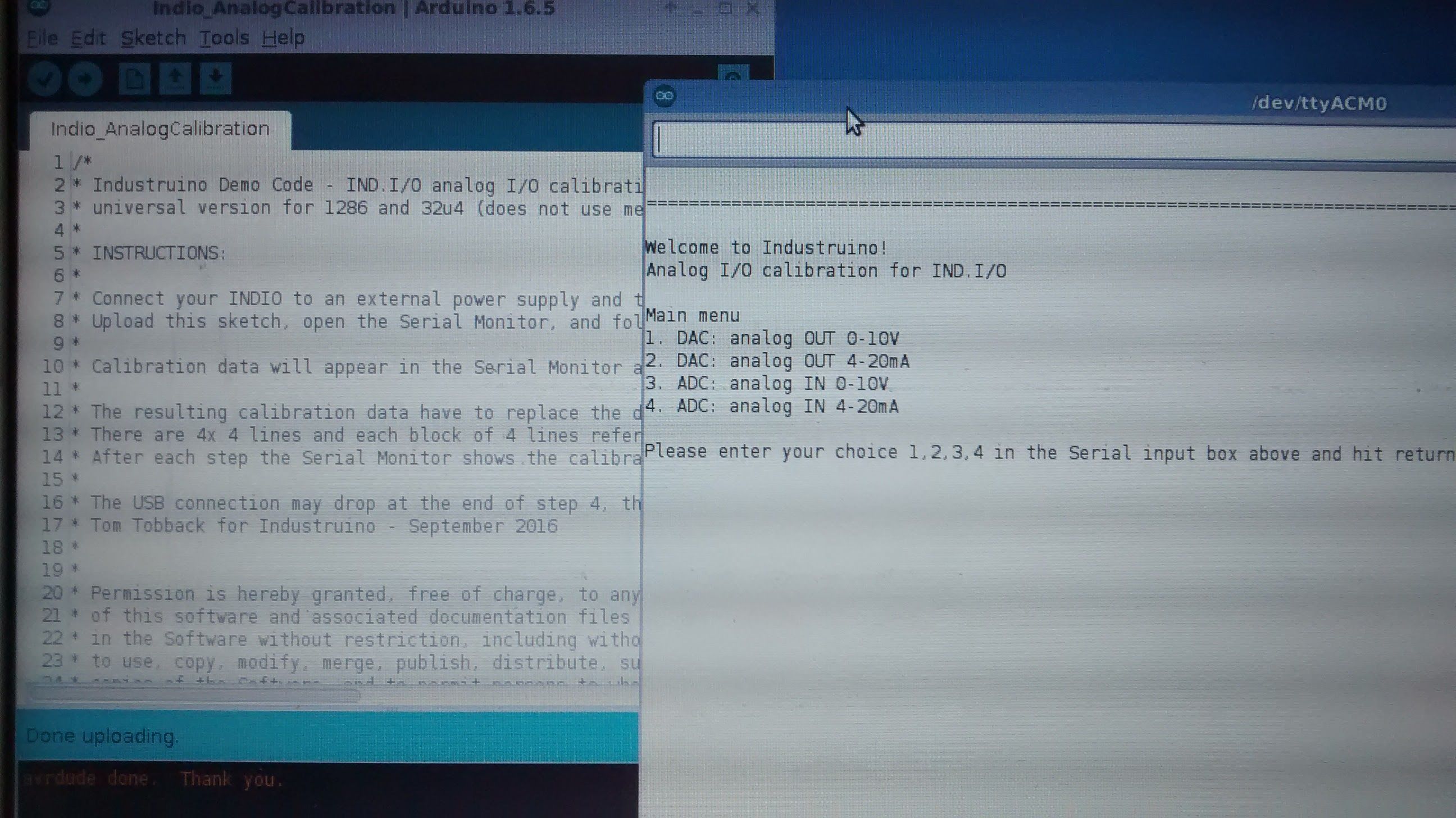
We have written a SKETCH to make this easier. The sketch is available here. It works for both the 32u4 and 1286 versions of the Industruino IND.I/O.
- Connect your Industruino to the external power supply, and to your computer via USB
- Upload this sketch using the Arduino IDE (select your Board type and Port)
- Open your Serial Monitor; this should show you the text as in this picture (sketch on left, Serial Monitor on right)
- In case you want to calibrate for the 4 options, execute them in the suggested order
- If you are only interested in e.g. 4.20mA output, you can jump to the relevent option
- Pay attention to enter the data in milliVolts (mV) and microAmperes (uA)
- At the end of each option you get the 4 lines with calibration data
- Note them down, or have your Indio.cpp file open to update the values directly
- In the Indio.cpp file, the first field of the array should be left at 0
- Save your Indio.cpp file with the new values
- When you compile your own sketch it will use your calibration data
Additional information on how to connect your hardware:
ANALOG I/O channels are on the top side of the Industruino
DAC voltage output 0-10V:
Use a digital multimeter to measure the voltage on the analog output channels: black to GND and red to CH1 or CH2.
DAC current output 4-20mA:
Use a digital multimeter to measure the current output: connect multimeter between output (CH1 or CH2) and GND, with a 100-500 Ohm resistor in series.
ADC voltage input 0-10V:
Feed a known voltage between 0-10V (low and high) into the 4 input channels at the same time: GND and CH1-4.
ADC current input 4-20mA:
Feed a known current between 0-20mA (low and high) into the 4 input channels one by one.
As a current source you can for example use a 500 Ohm resistor in series with a 0-20V voltage source (V+ and V-) and digital multimeter in series:
V+ -> 500 Ohm resistor -> multimeter -> CH1 and V- to GND on the Industruino
Change the value of the resistor to get a low current (e.g. around 10mA) and high current (e.g. around 20mA).